4-56 4252490-Rev A
ELECTRICAL
4
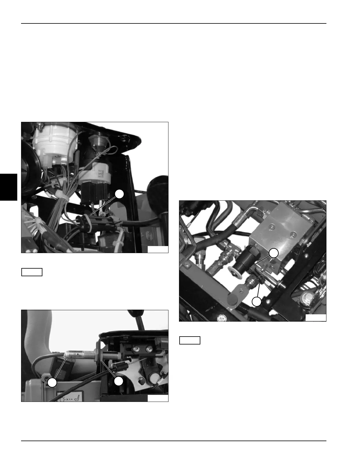
Mow/Transport Switch
Removal and Installation
See Figures 4-46 and 4-47.
1. Park the mower safely. (See “Park Mower Safely” on
page 1-6.)
2. Disconnect the negative (–) battery cable at the
battery.
3. Remove instrument panel cover. (See “Instrument
Panel Cover” on page 9-13.)
Figure 4-46
NOTE
Label all wires before disconnecting to ensure correct
installation.
4. Disconnect wire connector (1).
Figure 4-47
5. Remove nut (3).
6. Remove mow/transport switch (2).
Installation Notes
• Apply dielectric grease (Jacobsen PN 365422) to any
wire connectors disconnected.
• Use new cable ties to secure wire connectors and
wire harness.
• Install mow/transport switch assembly by reversing
the order of removal.
• Adjust the mow/transport switch. (See
“Mow/Transport Switch Adjustment” on page 4-49.)
Backlap Switch
Removal and Installation
See Figure 4-48.
1. Park the mower safely. (See “Park Mower Safely” on
page 1-6.)
2. Disconnect the negative (–) battery cable at the
battery.
3. Rotate seat forward. (See “Rotate Seat Forward” on
page 9-4.)
Figure 4-48
NOTE
Label all wires before disconnecting to ensure correct
installation.
4. Disconnect wire connector (2).
5. Remove backlap switch (1).
Installation Notes
• Apply dielectric grease (Jacobsen PN 365422) to any
wire connectors disconnected.
• Tighten backlap switch to 3–5 lb-ft (4–7 N·m).
• Install backlap switch by reversing the order of
removal.
TN3889
1
TN3892
3
2
TN3859
1
2

 Loading...


