ELECTRICAL
4252490-Rev A 4-59
4
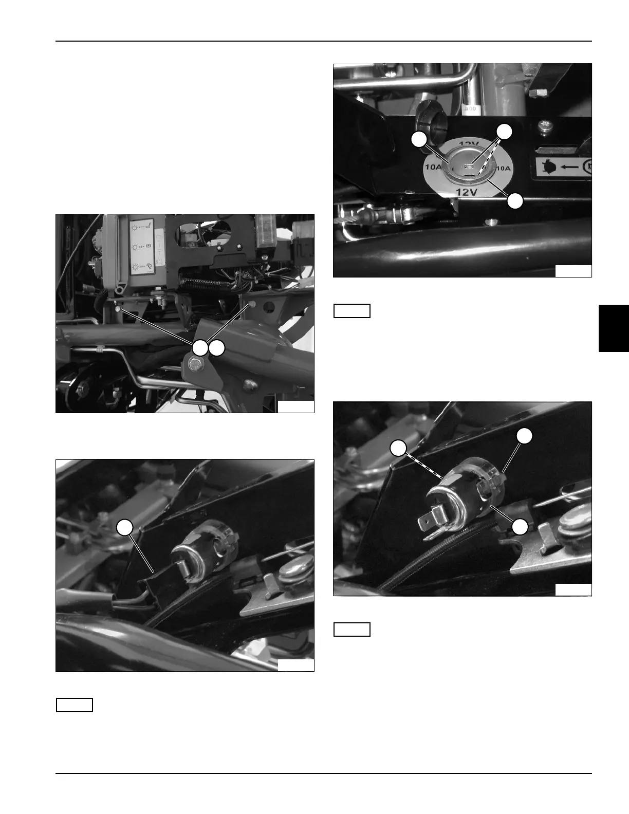
12V Accessory Socket
Removal and Installation
See Figures 4-52 through 4-55.
1. Park the mower safely. (See “Park Mower Safely” on
page 1-6.)
2. Disconnect the negative (–) battery cable at the
battery.
3. Remove instrument panel cover. (See “Instrument
Panel Cover” on page 9-13.)
Figure 4-52
4. Remove screws (1) and flat washers (2).
Figure 4-53
NOTE
Label all wires before disconnecting to ensure correct
installation.
5. Disconnect wire connector (3).
Figure 4-54
NOTE
Note orientation of the 12V accessory socket insert to
ensure correct installation.
6. Press tabs (5) and pull up on 12V accessory socket
insert (4), removing it from 12V accessory socket
base (6).
Figure 4-55
NOTE
Note orientation of the 12V accessory socket base to
ensure correct installation.
7. Press tabs (7) and push 12V accessory socket base
(6) through instrument panel.
TN3939
1 2
TN3938
3
TN3940
5
4
6
TN3942
7
7
6

 Loading...


