ELECTRICAL
4252490-Rev A 4-53
4
Rocker Switches
Removal and Installation
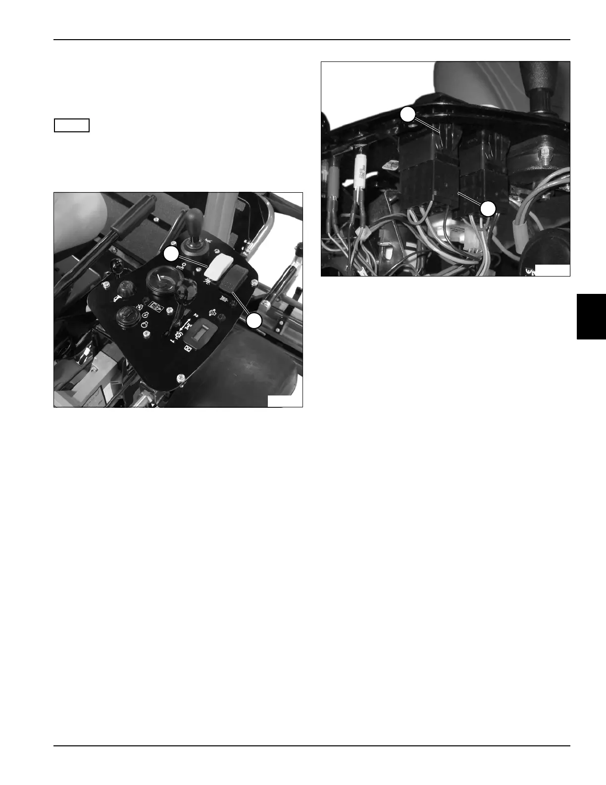
See Figures 4-40 and 4-41.
NOTE
This procedure applies to the following switches:
• Mow switch (1)
• Light switch (2)
Figure 4-40
1. Park the mower safely. (See “Park Mower Safely” on
page 1-6.)
2. Disconnect the negative (–) battery cable at the
battery.
3. Remove instrument panel cover. (See “Instrument
Panel Cover” on page 9-13.)
Figure 4-41
4. Disconnect wire connector (4).
5. Depress taps (3) on each side of rocker switch and
remove rocker switch from instrument panel.
Installation Notes
• Apply dielectric grease (Jacobsen PN 365422) to any
wire connectors disconnected.
• Use new cable ties to secure wire connectors and
wire harness.
• Install rocker switches by reversing the order of
removal.
2
1
TN3884
4
3
TN3887

 Loading...


