ELECTRICAL
4252490-Rev A 4-55
4
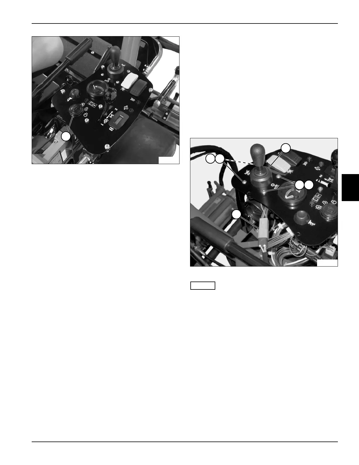
Figure 4-44
7. Remove retaining nut (4).
8. Remove key switch.
Installation Notes
• Key switch has mounting tabs that fit into the
instrument panel. When installing, make sure key
switch is properly mounted.
• Apply dielectric grease (Jacobsen PN 365422) to any
wire connectors disconnected.
• Use new cable ties to secure wire connectors and
wire harness.
• Install key switch by reversing the order of removal.
Raise/Lower Switch Assembly
Removal and Installation
See Figure 4-45.
1. Park the mower safely. (See “Park Mower Safely” on
page 1-6.)
2. Disconnect the negative (–) battery cable at the
battery.
3. Remove instrument panel cover. (See “Instrument
Panel Cover” on page 9-13.)
4. Remove instrument panel. (See “Instrument Panel”
on page 4-52.)
Figure 4-45
NOTES
• Note orientation of the raise/lower switch assembly
to ensure correct installation.
• Label all wires before disconnecting to ensure
correct installation.
5. Remove screws (1) and nuts (2).
6. Disconnect wire connector (4).
7. Remove raise/lower switch assembly (3).
Installation Notes
• Apply dielectric grease (Jacobsen PN 365422) to any
wire connectors disconnected.
• Use new cable ties to secure wire connectors and
wire harness.
• Install raise/lower switch assembly by reversing the
order of removal.
TN3884
4
TN3891
1
1 2
2
4
3

 Loading...


