6-48 4252490-Rev A
HYDRAULICS
6
Reel Valve Unit
Removal and Installation
See Figures 6-50 and 6-51.
1. Park the mower safely. (See “Park Mower Safely” on
page 1-6.)
2. Drain hydraulic oil tank. (See “Hydraulic Oil Tank—
Drain Procedure” on page 6-42.)
NOTE
The reel valve unit is located below the seat plate.
3. Remove seat and seat plate. (See “Seat and Seat
Plate” on page 9-15.)
4. Thoroughly clean the valve, especially the area
surrounding hydraulic hoses, tubes, and fittings.
Figure 6-50
NOTE
Label wire connector before disconnecting to ensure
correct installation.
5. Disconnect wire connector (1) from mow solenoid.
NOTES
• Label all hydraulic hoses and tubes before
disconnecting to ensure correct installation.
• Close all openings with caps or plugs to prevent
contamination.
6. Disconnect hydraulic tubes (2 and 3).
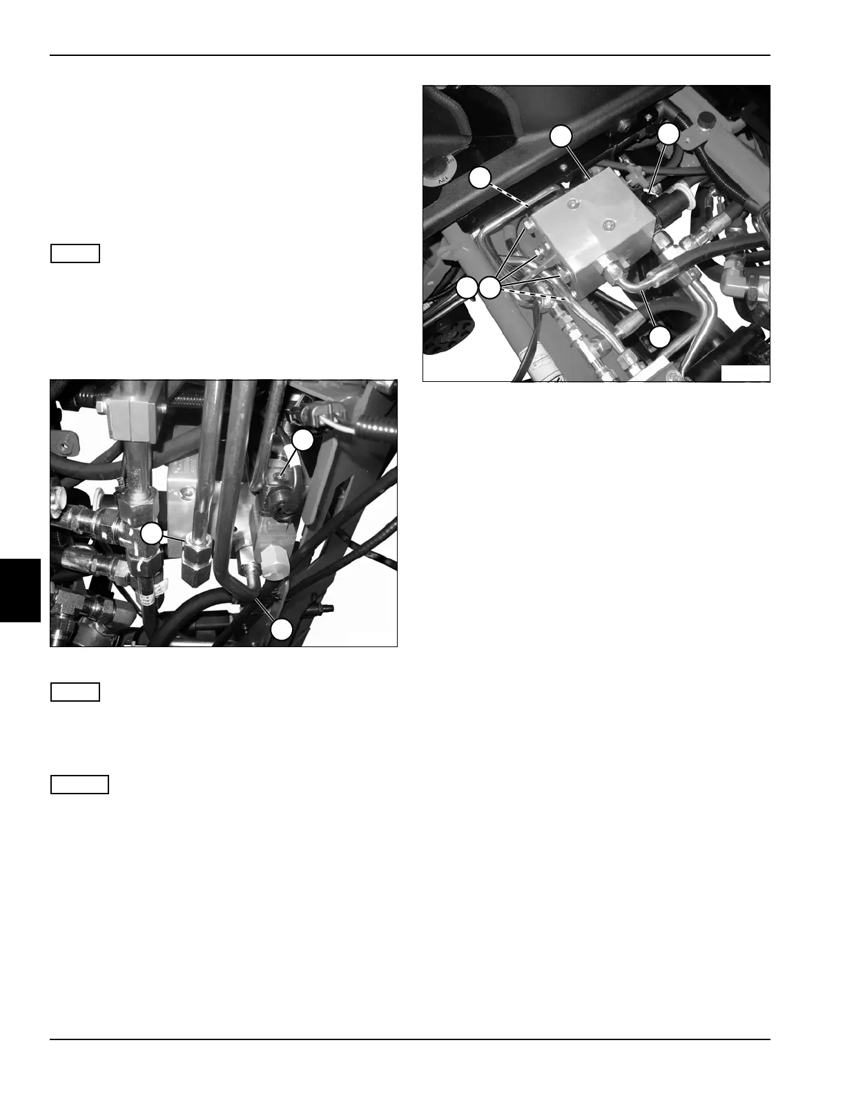
Figure 6-51
7. Disconnect backlap switch wire connector.
8. Support the reel valve unit (5).
9. Disconnect hydraulic tubes (4 and 7).
10. Remove four mounting screws (8) and washers (9).
11. Remove reel valve unit (5).
Installation Notes
• Install reel valve unit by reversing the order of
removal.
• Make sure new O-rings are in place before installing
hoses on fittings.
• Apply dielectric grease (Jacobsen PN 365422) to any
wire connectors disconnected.
• Replace hydraulic oil charge filter. (See “Hydraulic
Oil Charge Filter Assembly” on page 6-59.)
• Refill hydraulic tank. (Refer to “Parts and
Maintenance Manual” for correct oil specifications.)
• Start engine. Check hydraulic system for leaks.
Repair as necessary.
• Check hydraulic oil level and add if necessary.
TN3903
2
1
3
TN3779
7
6
5
4
9
8

 Loading...


