HYDRAULICS
4252490-Rev A 6-49
6
Disassembly, Inspection, and Assembly
See Figures 6-52 and 6-53.
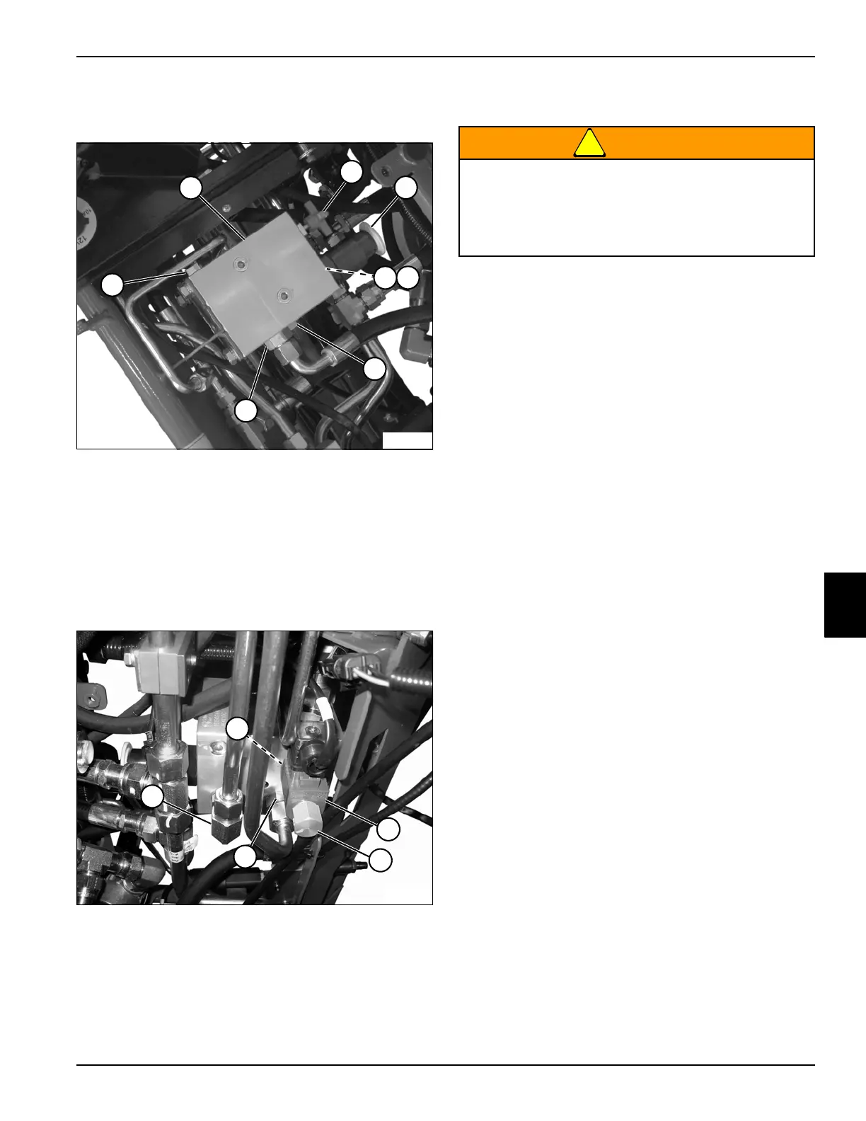
Figure 6-52
12. Remove, inspect, and replace fitting (7) from port “P”
as necessary.
13. Remove, inspect, and replace fitting (8) from port “T”
as necessary.
Figure 6-53
14. Remove, inspect, and replace fitting (12) from port
“A” as necessary.
15. Remove, inspect, and replace fitting (9) from port “B”
as necessary.
!
WARNING
16. Clean all parts using clean solvent, and dry using
compressed air.
17. Inspect all parts for wear or damage. Replace parts
as necessary.
1 Reel Valve Unit Block 5 Check Valve
2 Speed Control Valve 6 Pressure Compensating Valve
3 Reel (Backlap) Valve 7 Port Fitting P
4 Orifice 8 Port Fitting T
9 Port B Fitting 12 Coil Nut
10 Mow/Relief Valve 13 Port A Fitting
11 Mow Solenoid
TN3971
3
2
1
7
8
4
6
5
TN3903
9
13
11
10
12
Use appropriate eye protection when using
compressed air for cleaning or drying purposes.
Compressed air can cause serious personal
injury. Use safety reduction valves to reduce the
air pressure to a safe level before use.

 Loading...


