9-20 4252490-Rev A
ACCESSORIES AND MISCELLANEOUS REPAIR
9
Installation Notes
• Inspect and clean any rust from hub or wheel
mounting area.
• Install wheel by reversing the order of removal.
• Tighten mounting bolts to 55 lb-ft (75 N·m) using an
alternating pattern.
• Set tire pressure to 10 psi (0.7 bar).
Park Brake Caliper Assembly
Removal and Installation
See Figure 9-43.
NOTE
Right wheel park brake caliper assembly is shown; left
wheel park brake caliper assembly is similar.
1. Park the mower safely. (See “Park Mower Safely” on
page 1-6.)
2. Remove front wheel. (See “Front Wheel” on
page 9-19.)
3. Disengage park brake.
Figure 9-43
4. Remove pin (1) and clip (2).
5. Remove two screws (4) and flat washers (5).
6. Remove park brake caliper assembly (3).
Installation Note
Install park brake caliper assembly by reversing the order
of removal.
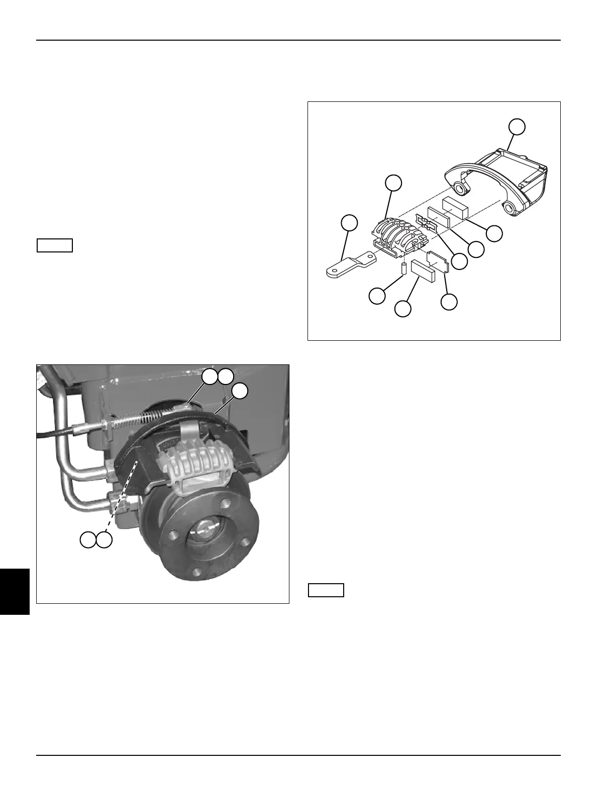
Disassembly and Assembly
See Figure 9-44.
Figure 9-44
1. Remove caliper housing (2) from caliper bracket (3).
2. Remove pin (9) and cam (1).
3. Remove pad support (7) and brake pad (8).
4. Remove retainer (6), pad support (5), and brake pad
(4).
5. Inspect brake pads for excessive or uneven wear.
Replace as a set if necessary.
Assembly Note
Assemble park brake caliper in reverse order of
disassembly.
Park Brake Cables
Removal and Installation
See Figures 9-45 through 9-48.
NOTE
Right park brake cable shown; left park brake cable is
similar. To access left park brake cable, remove tool box.
(See “Tool Box” on page 9-17.)
1. Park the mower safely. (See “Park Mower Safely” on
page 1-6.)
2. Remove instrument panel cover. (See “Instrument
Panel Cover” on page 9-13.)
3. Block each side of front wheels using suitable wheel
blocks.
4. Disengage park brake.
54
3
21
TN3663
1
2
3
4
5
6
7
8
9
TN3861

 Loading...


