HYDRAULICS
4252490-Rev A 6-47
6
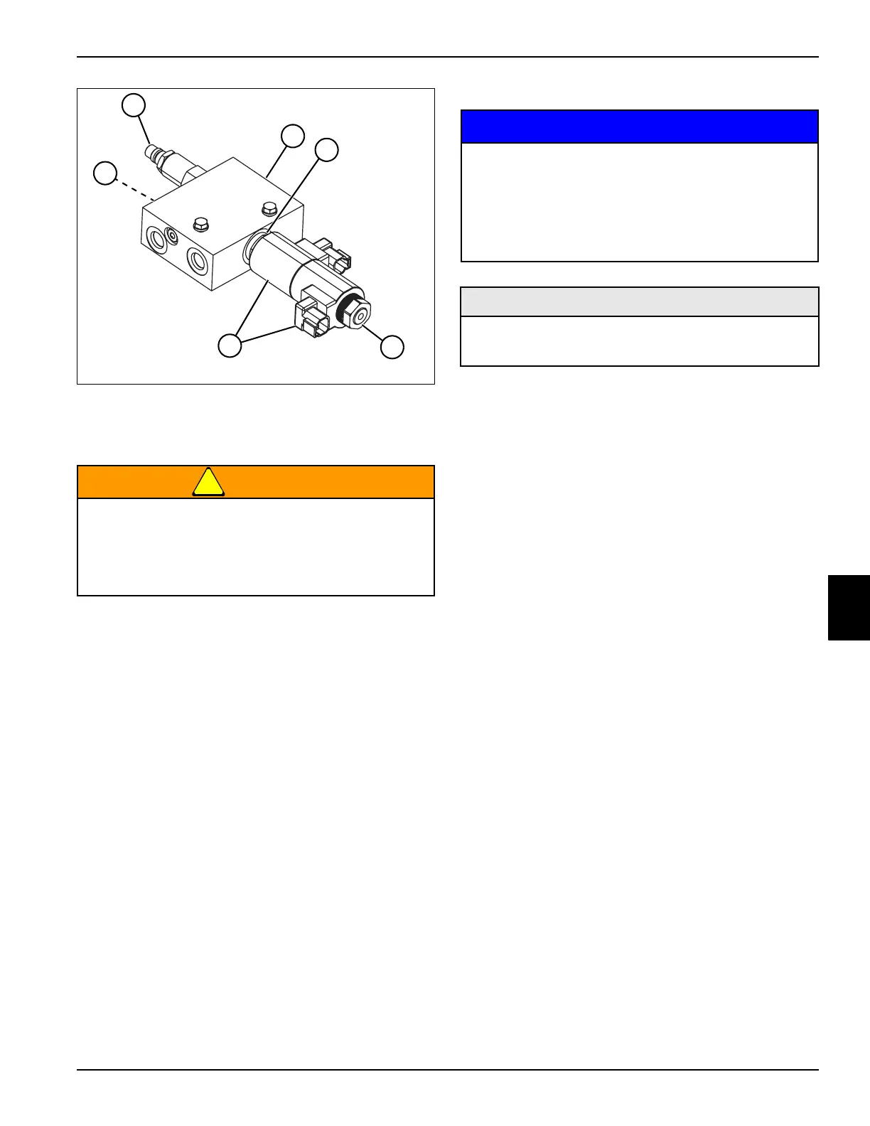
Figure 6-49
!
WARNING
4. Clean all parts using clean solvent, and dry using
compressed air.
5. Inspect all parts for wear or damage. Replace parts
as necessary.
Assembly Notes
NOTICE
• Assemble lift valve by reversing the order of
disassembly.
• Use a new seal kit and solenoid valve O-ring during
assembly.
• Lubricate all O-rings prior to assembly.
• Tighten coil nut (9) to 35–53 lb-in. (4–6 N·m).
• Tighten relief valve (6) to 20–25 lb-ft
(27–34 N·m).
• Tighten solenoid valve (8) to 25–30 lb-ft
(34–40 N·m).
• Tighten check valve (5) to 30–35 lb-ft
(41–47 N·m).
• Tighten fittings for ports “P” (2) and “T” (1) to 55 lb-ft
(74 N·m).
• Tighten fittings for ports “A” (4) and “B” (3) to 17 lb-ft
(23 N·m).
5 Check Valve 8 Solenoid Valve
6 Relief Valve 9 Nut
7 Lift Valve Block 10 Coils
Use appropriate eye protection when using
compressed air for cleaning or drying purposes.
Compressed air can cause serious personal
injury. Use safety reduction valves to reduce the
air pressure to a safe level before use.
TN3808
5
6
7
10
9
8
It is important that all component parts are
absolutely clean, as contamination can result in
serious damage and/or improper operation.
Never use shop towels or rags to dry parts after
cleaning, as lint may clog passages. Dry parts
using compressed air.
Required Materials
•Seal Kit
• Solenoid Valve O-Ring

 Loading...


