5-68 4252490-Rev A
HYDROSTATIC POWER TRAIN
5
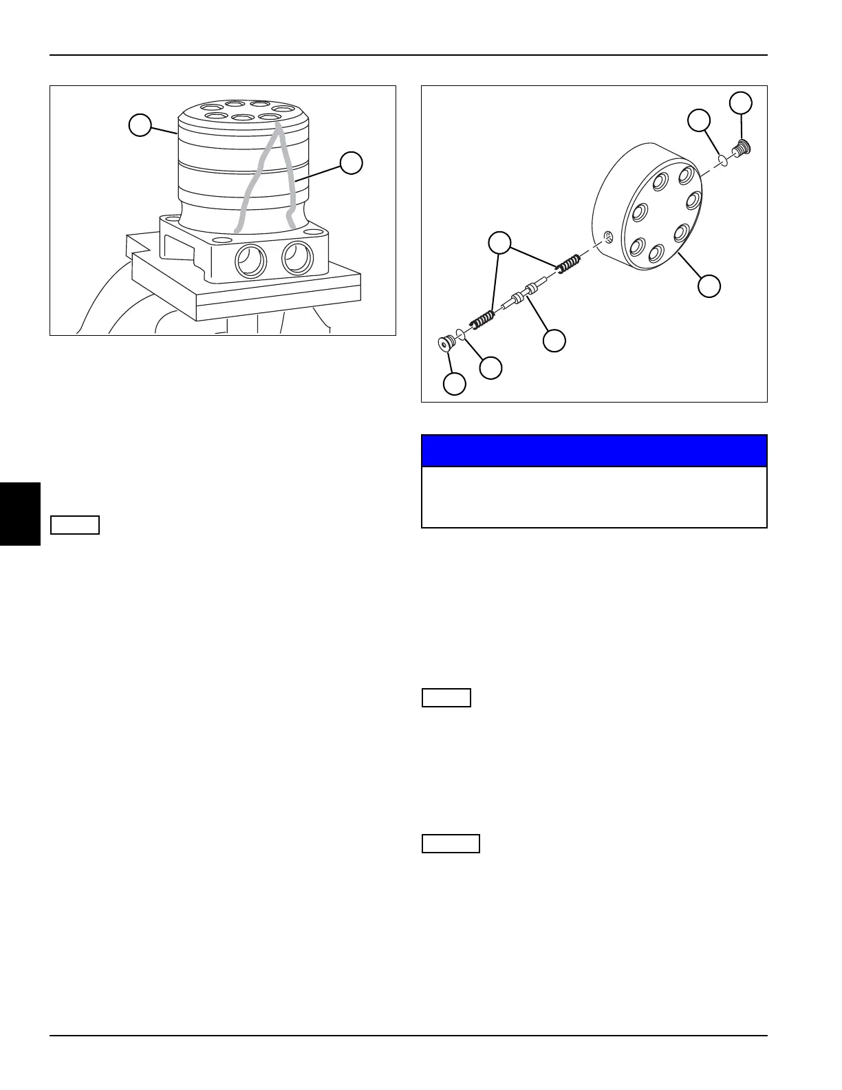
Figure 5-71
1. Place wheel motor (28) in a soft-jawed vice, with the
coupling shaft pointed down and the vise jaws firmly
clamping each side of the housing mounting flange.
2. Scribe or mark lines (29) across the side of wheel
motor sections to mark the position and orientation of
motor segments before disassembly.
3. Loosen, but do not remove, the two shuttle valve
plugs (24 and 27).
NOTE
Use caution when removing screws, as motor segments
will be free to move.
4. Remove seven screws (25) from end cover (23).
5. Inspect screws (25) and seal rings (26) for damage.
Replace as needed.
6. Remove end cover (23) and seal ring (14) from
commutator (20) and commutator ring (22).
7. Inspect the surface of the end cover that makes
contact with commutator and commutator ring. A
polished pattern (not scratches) from the commutator
is normal. Discoloration indicates excess fluid
temperature, thermal shock, or excess speed and
requires inspection of the end cover, commutator,
manifold, and rotor set. Replace as needed.
Figure 5-72
NOTICE
8. Remove two shuttle valve plugs (24 and 27) and
O-rings (30 and 32).
9. Remove shuttle valve (31) and two springs (33).
10. Remove commutator ring (22) and commutator (20).
11. Remove seal ring (21) from commutator (20) using
compressed air to blow air into the ring groove until
the seal ring is lifted out of the groove.
NOTE
If any damage or wear is noticed in the commutator or
commutator ring, both must be replaced as a matched
set.
12. Inspect commutator ring (22) for cracks or burrs.
13. Inspect commutator (20) for cracks, burrs, wear,
scoring, spalling, or brinelling.
NOTES
• The manifold is constructed of plates bonded
together to form an integral component and must not
be disassembled.
• Compare the configuration of each side of the
manifold and note which side of the manifold is
positioned against the rotor set to ensure correct
installation.
14. Remove manifold (19).
TN3890
28
29
Shuttle valve components are spring-loaded and
will fall out as the plugs are removed. Remove
plugs slowly, and be ready to catch components.
TN3898
~
30
24
3
33
31
32
27

 Loading...


