HYDROSTATIC POWER TRAIN
4252490-Rev A 5-73
5
NOTE
Two alignment studs, installed finger-tight into two of the
screw holes, 180° apart, may be used to aid in assembly.
These studs can be made by cutting the heads from
5/16-24 UNF 2A bolts, that are 0.50 in. (12.7 mm) longer
than the screws (25) used to hold the motor together.
13. Install drive link (11) in coupling shaft (9), engaging
the splines with splines on the coupling shaft.
14. Apply a thin film of petroleum jelly to seal ring (14),
and install seal ring in the groove on housing (3).
15. Apply a thin film of petroleum jelly to seal ring (14),
and install seal ring in the groove in the wear plate
side of the stator half (16).
NOTE
It may be necessary to remove one of the alignment
studs temporarily to install the rotor set/wear plate
assembly.
16. Install rotor set (13) on the wear plate (15), with the
counterbore and seal ring side toward the wear plate.
17. Install the rotor set and wear plate assembly over
drive link (11). Make sure that drive link splines
engage with rotor splines.
18. Apply a thin film of petroleum jelly to seal ring (14),
and install seal ring in the groove on the side of the
manifold (19) facing the rotor set.
NOTE
The manifold surface that must make contact with the
rotor set has a series of irregular shaped cavities on the
outside diameter. The surface may also have a polished
impression left by contact with the rotor set.
19. Install manifold (19) on rotor set (13).
20. Apply a thin film of petroleum jelly to seal ring (14),
and install seal ring in the groove in the manifold
(19).
21. Install commutator ring (22) on manifold (19).
22. Install a new seal ring (21), with the flat side up, in
the commutator (20).
23. Install commutator (20) over drive link (11), with the
seal ring side away from the manifold.
Figure 5-77
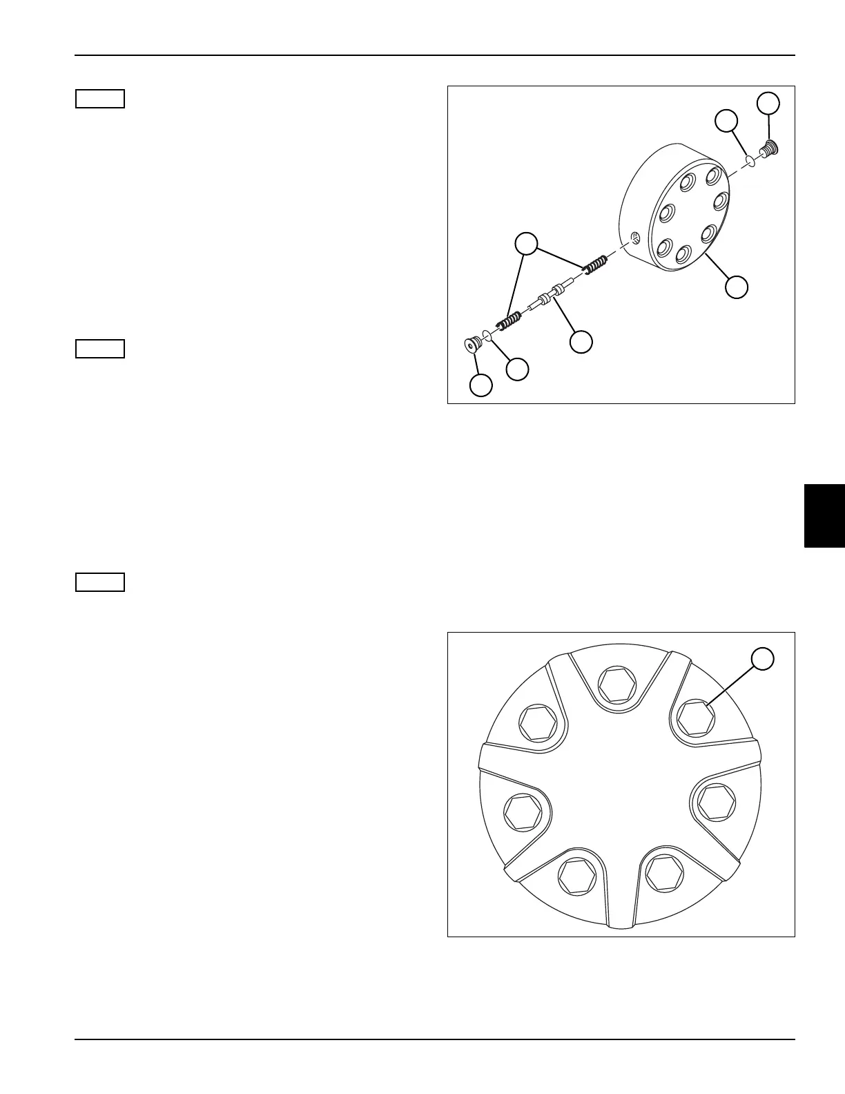
24. Install shuttle valve (30) and two springs (32).
25. Install two shuttle valve plugs (24 and 26) and
O-rings (29 and 31).
26. Apply a thin film of petroleum jelly to seal ring (14),
and install seal ring in the groove in the end cover
(23).
27. Install screws (25) in the motor, and tighten
fingertight.
28. Remove the alignment studs, and install the
remaining screws (25).
Figure 5-78
29. Tighten seven screws (25) in stages, using an
alternating pattern, to a final torque of 50–55 lb-ft
(68–75 N·m).
TN3898
~
29
24
23
32
30
31
26
TN3904
25

 Loading...


