6-44 4252490-Rev A
HYDRAULICS
6
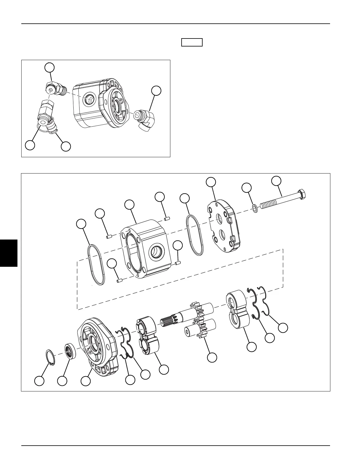
Disassembly, Inspection, and Assembly
See Figures 6-44 through 6-46.
Figure 6-44
NOTE
Record the location of fittings before removing to ensure
correct installation.
1. Remove, inspect, and replace dust cover (3) and tee
fitting (4) as necessary.
2. Remove, inspect, and replace outlet port fitting (1) as
necessary.
3. Remove, inspect, and replace inlet port fitting (2) as
necessary.
Figure 6-45
TN3867
2
1
3
4
5 Body Seal (2) 8 Rear Cover 11 Backup Ring (2) 14 Gear Set (Drive Shaft) 17 Retaining Ring
6 Dowel Pin (4) 9 Washer (4) 12 Seal (2) 15 Front Cover/Flange
7 Body 10 Retaining Screw (4) 13 Thrust Plate (2) 16 Shaft Seal
TN3865
10
6
6
5
8
5
14
12
11
17
15
16
7
9
11
13
12
6
13
6

 Loading...


