6-62 4252490-Rev A
HYDRAULICS
6
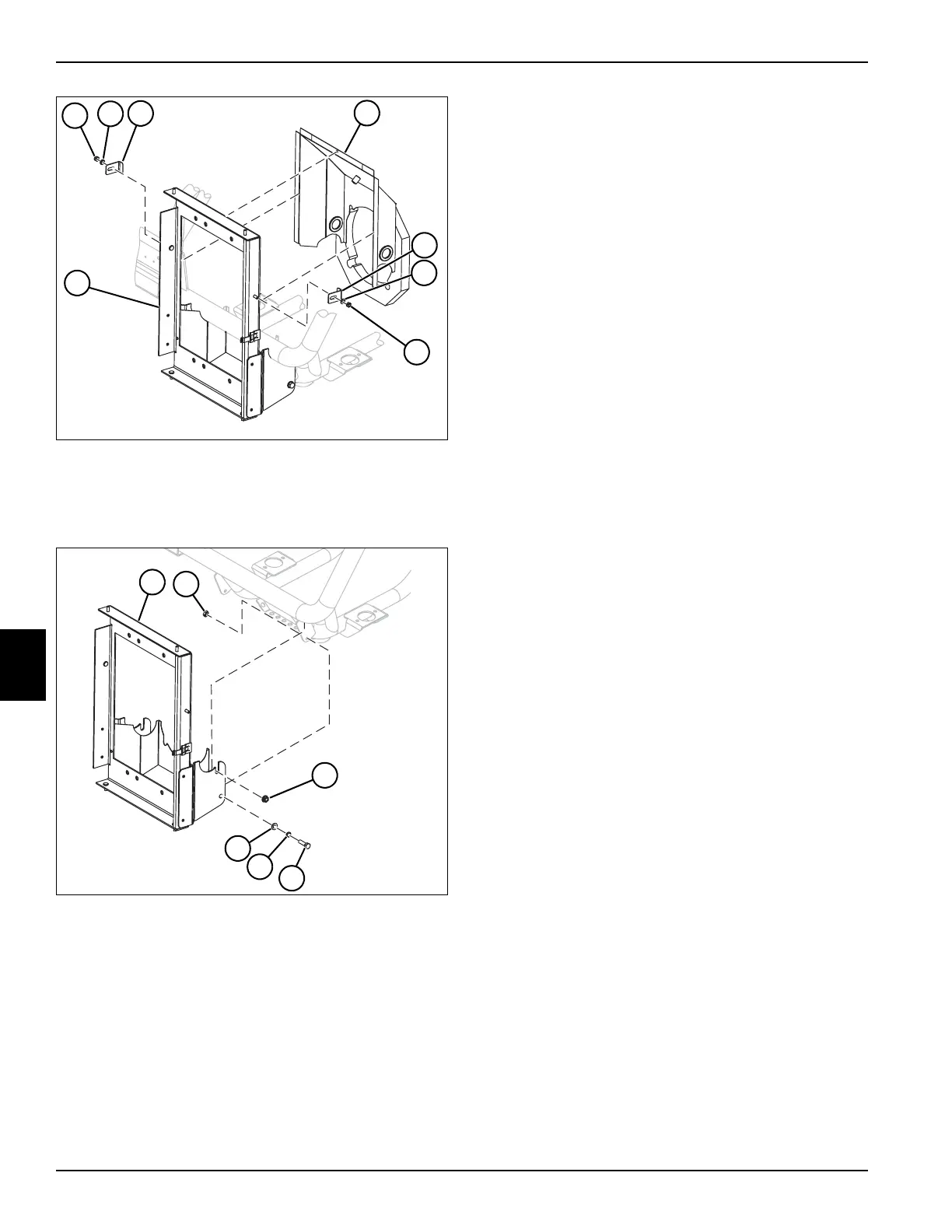
Figure 6-80
12. Remove two nuts (19), washers (20), and clamps
(21), and remove air intake cover assembly (22) from
cooler frame (23).
Figure 6-81
13. Support the cooler frame (23) using a suitable lifting
device.
14. Remove two nuts (25).
15. Remove two nuts (24), screws (26), lock washers
(27), and flat washers (28), and remove oil cooler
frame (23) from the machine.
Installation Notes
• Install oil cooler by reversing the order of removal.
• Make sure new O-rings are in place before installing
hoses and fittings.
• Replace hydraulic oil charge filter. (See “Hydraulic
Oil Charge Filter Assembly” on page 6-59.)
• Refill hydraulic tank. (Refer to “Parts and
Maintenance Manual” for correct oil specifications.)
• Start engine. Check hydraulic system for leaks.
Repair as necessary.
16. Check hydraulic oil level and add if necessary.
TN3857
22
19
20
21
23
21
20
19
TN3856
23
24
25
28
27
26

 Loading...


