Troubleshooting and diagnostic options
TR-Electronic GmbH 2019, All Rights Reserved Printed in the Federal Republic of Germany
Page 140 of 154 TR - ECE - BA - GB - 0139 - 02 11/21/2019
9 Troubleshooting and diagnostic options
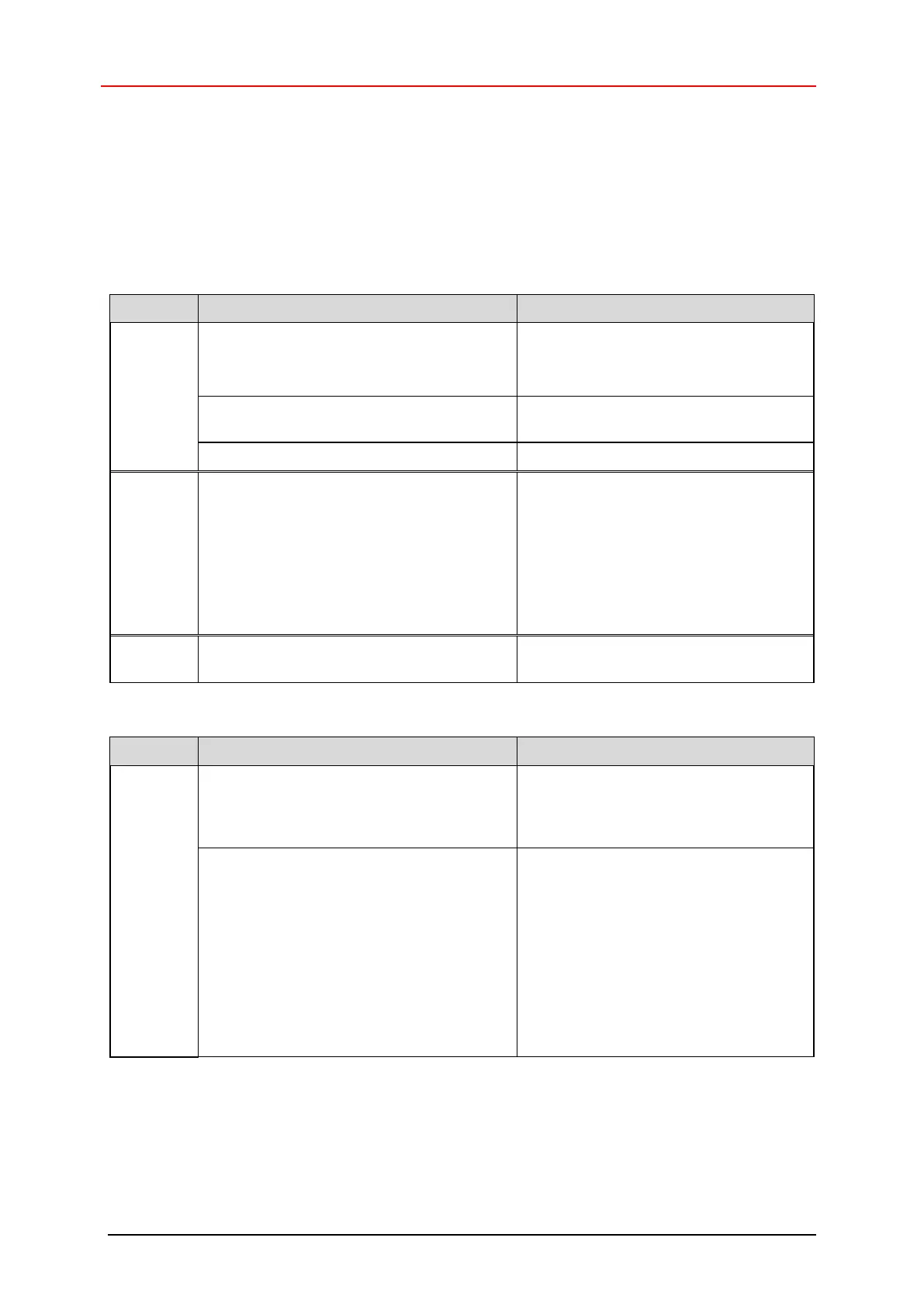
9.1 Optical displays
The position and assignment of the LEDs can be found in the accompanying pin assignment.
9.1.1 Device status, Bicolor LED
Voltage supply absent or too low
- Check power supply, wiring
- Is the voltage supply in the permissible
range?
Connector incorrectly wired or screwed
down
Check wiring and connector position
Hardware error, measuring system defective
- Measuring system could not synchronize
with the F Host in the start-up phase and
requests a re-integration (user
acknowledgment)
- An error has been detected in the safety-
related communication or a
parameterization error has been detected,
which has been eliminated
Re-integration of the designated variable
is required via the safety program.
See also bit 1 OA_Req in the
SafeControl byte on Page 133.
Normal mode, measuring system in data
exchange
A safety-relevant error was detected, the
measuring system was put into fail-safe
state and outputs its passivated data:
To restart the measuring system after
passivation, eliminate the error first
and then switch the supply voltage
OFF/ON.
- Error in safety-related communication
- Try to localize the error using
diagnostic variables (depending on the
control)
- Check that the set value for the
F_WD_Time parameter is appropriate
for the automation task; see Chapter
“F_WD_Time” on Page 136
- Check whether the PROFINET
connection between F-CPU and
measuring system is faulty
Continued on next page

 Loading...