Printed in the Federal Republic of Germany TR-Electronic GmbH 2019, All Rights Reserved
11/21/2019 TR - ECE - BA - GB - 0139 - 02 Page 99 of 154
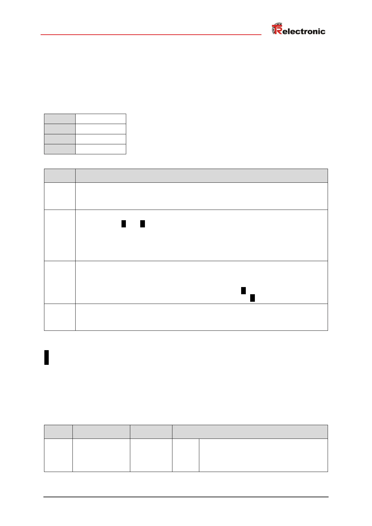
6.4.5 Submodule status
6.4.5.1 Structure of the cyclic process data
Structure of input data, IO device -> master
Unsigned8
Velocity overflow
0: no velocity overflow
1: velocity overflow present
Output of the original position
0: own channel A
1)
or B
1)
in error state -> output of the substitute position
1: Output of the original position, either
-> via channel 1 (master system) or
-> via channel 2 (test system),
depending on the mapping of the sub-module configuration
Output of the substitute position
0: own channel has no error -> output of the original position
1: Output of the substitute position, either
-> via channel 2 (test system) in case of error constellation A or
-> via channel 1 (master system) in case of error constellation B
Legacy mode
0: Measuring system is not operated in the Legacy mode
1: Measuring system is operated in the Legacy mode
__________________
1)
A : Channel 1 (master system)
B : Channel 2 (test system)
6.4.5.2 Configurable submodule-related parameters
The Parameters can be set according to the following table via an input box in the configuration tool
and are automatically sent by the control to the measuring system during start-up via the record data
object with index 0x0001.
Output of the substitute position if the own
channel is in error state
0: off
1: on