Printed in the Federal Republic of Germany TR-Electronic GmbH 2019, All Rights Reserved
11/21/2019 TR - ECE - BA - GB - 0139 - 02 Page 37 of 154
6.2.1.5 Format Signal 6 / 8: Actual speed value A / B (NIST_A / B)
The velocity is output as a two's complement value with preceding sign.
Code sequence set to = CW
Looking at the flange connection, turn the shaft clockwise:
--> positive velocity output
Code sequence set to = CCW
Looking at the flange connection, turn the shaft clockwise:
--> negative velocity output
The unit is set via the parameter Velocity value normalization (PNU 60001), see Page 50.
The default setting is Revolutions per minute.
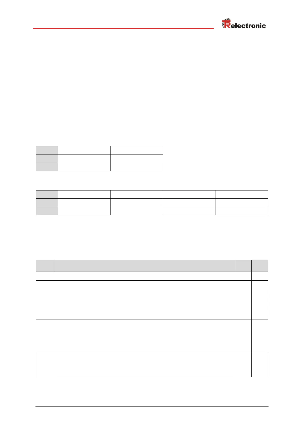
NIST_A, Integer16
NIST_B, Integer32
6.2.1.6 Format Signal 9: Control word, Sensor 1 (G1_STW)
The control word G1_STW controls the basic measuring system functions:
Unsigned16
Preset mode
Defines whether the measuring system’s actual position value is set to the
preset value or if it should be offset by this value.
0: Position value is set to the preset value (absolute)
1: Position value is offset by the preset value (relative = offset)
Execute preset according to preset mode
The preset value is set with a rising edge 0->1. The exact procedure is
described in the Chapter “Preset function” on Page 70. In the default setting
signal G1_XIST1 remains unaffected, see parameter Preset affects
XIST1 on Page 47.
Cyclically request absolute position
0: No querying of absolute position
1: Absolute position is cyclically transmitted via the signal G1_XIST2
Continued on next page