Parameterization and configuration
TR-Electronic GmbH 2019, All Rights Reserved Printed in the Federal Republic of Germany
Page 96 of 154 TR - ECE - BA - GB - 0139 - 02 11/21/2019
6.4.3.2.1 Velocity format
Indicates the resolution at which the velocity is calculated and output.
The velocity is output signed, as a two's complement:
● Counting direction setting = forward
– Output positive, with clockwise rotation
(looking at flange connection)
● Counting direction setting = backward
– Output negative, with clockwise rotation
(looking at flange connection)
If the velocity value range (-2147483648…+2147483647) is exceeded or not reached, the limit values
(0x7FFF FFFF or 0x8000 0000) are output.
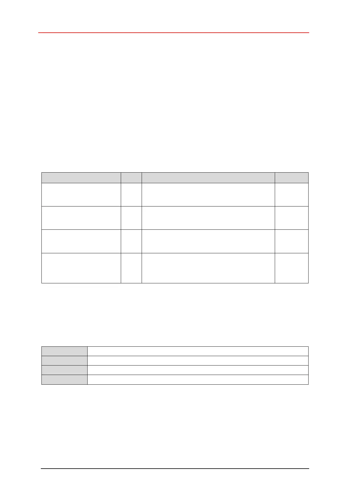
Output in [rev./second], multiplied by the factor
set under the Velocity factor parameter,
see Page 97
Output in [rev./minute], multiplied by the factor
set under the Velocity factor parameter,
see page 97
Output in [rev./hour], multiplied by the factor set
under the Velocity factor parameter, see
page 97
(steps/integration time) *
factor
Output in [steps/ms], multiplied by the factor set
under the Velocity factor parameter, see
page 97
Resolution : scaled steps/rev.
6.4.3.2.2 Velocity filter intensity
Using the Velocity filter intensity parameter, the output velocity can be averaged. The
parameter serves to setup a lowpass filter working on the measuring system’s actual velocity value.
Higher intensity values allow stronger filtering yielding to lower cut-off frequencies. High acceleration
motion profiles require lower filter intensities. Refer to the following described parameter Velocity
filter type, for a dynamic filter engagement according to the current motion status.
0: no filtering
1: weak filtering, high cut-off frequency
. . .
10: strong filtering, low cut-off frequency