Motion Coordinator Technical Reference Manual
System Setup and Diagnostics 6-5
Preliminary Concepts:
Example:
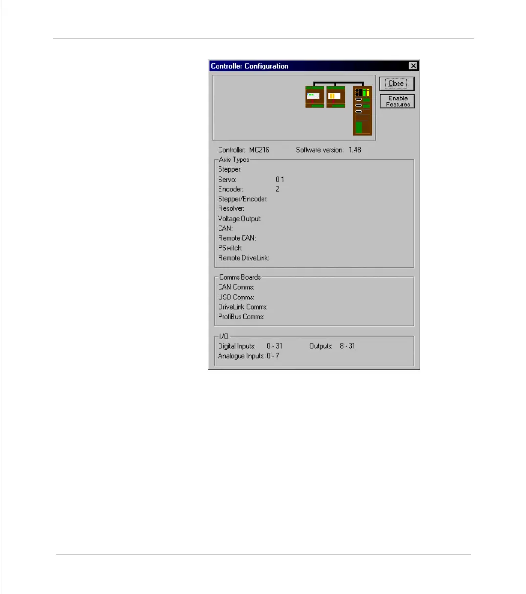
This message would be produced by a Motion Coordinator MC216 with the follow-
ing configuration:
•System Software version 1.48
• Two servo daughter boards in axis slots 0 and 1.
• A encoder daughter board in axis slot 2.
• A CAN16 I/O module, which adds a further 16 I/O channels, making a total of
32 channels (All 32 can be used as inputs, channels 8-31 are bidirectional and
may be used as input or output as required)
• A CAN Analog Inputs module providing input channels 0-7.
Check that the system description corresponds with the modules that are actually
present. If this is not so, check the CANBus and ribbon cable connections and the
settings of the address switches on any CAN or axis expander modules.
 Loading...