Motion Coordinator Technical Reference Manual
Introduction 1-11
System Building
System Building
The modules and boards may be mixed within the system rules:
1) Every system must start with one Motion Coordinator master unit as this contains
the processor and logic power supply for the system.
2) The MC216 master unit can house up to 4 daughter boards. The Euro 205 and
MC206 will accept a single daughter board. These can be of any type.
3) The MC216 can have up to 3 axis expander modules added to house up to 16
daughter boards. 4 being housed in the Master and 4 in each of the axis expand-
ers.
4) Up to 16 CAN-16 I/O and 4 CAN Analog Input modules can be connected to any
Motion Coordinator.
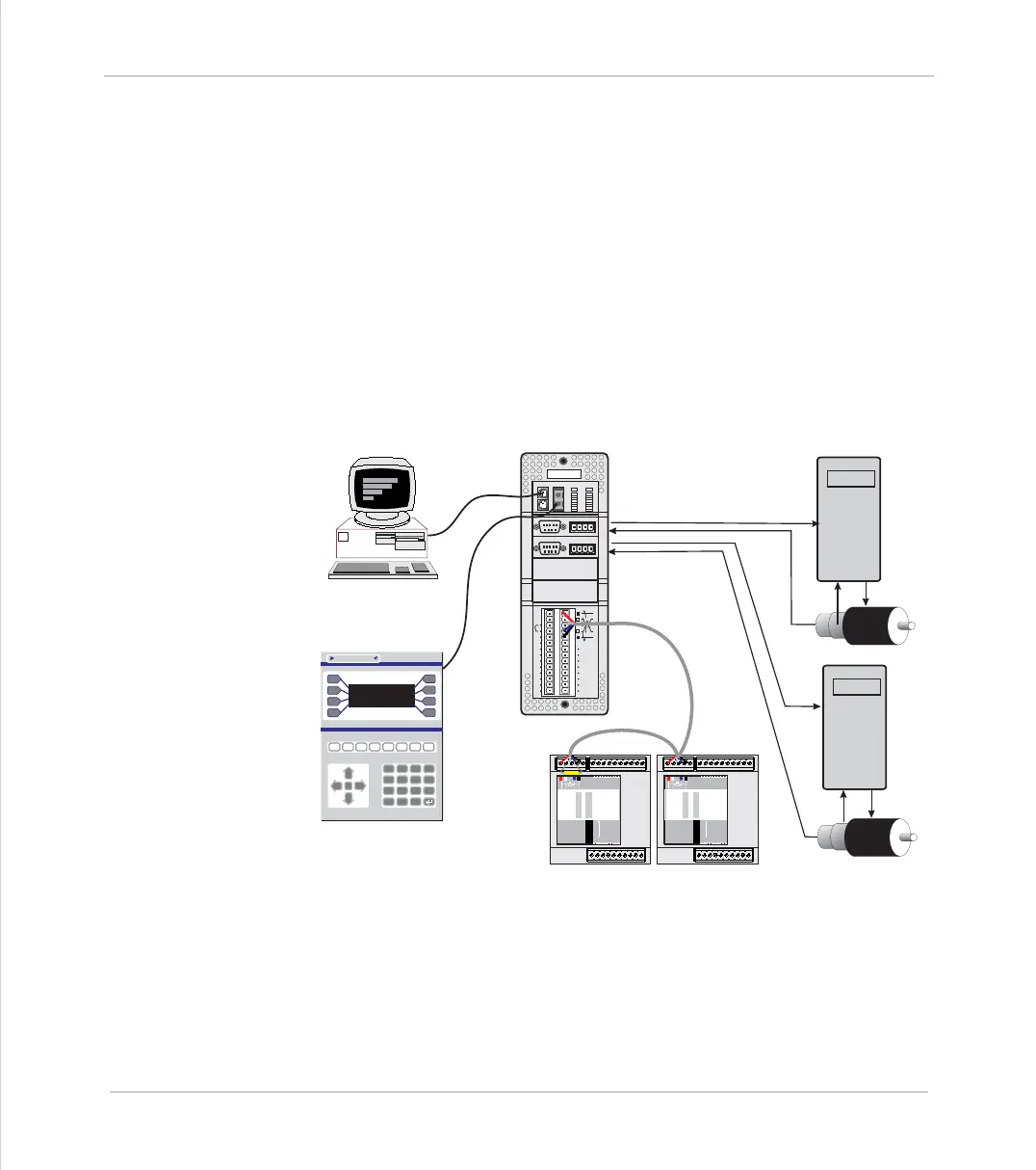
Typical System Configuration
ENCODER
V+ V- R
0v
54321
9876
ENCODER
V+ V- R
0v
54321
9876
IO8
IO9
IO10
IO11
IO12
IO13
IO14
IO15
I0
I1
I2
I3
I4
I5
I6
I7
24v
0v
Trio
8
9
10
11
12
13
14
15
0
OKNET
0
1
STA TUS
1
2
3
4
5
6
7
0
1
2
3
4
5
6
7
8
9
10
11
12
13
14
15
1
2
4
8
16
32
OFF
MS NS
PR
DR
10 11 12 13 14 15 24v Ov98
765432100v 24v
NODE
ADDRESS
CAN16 -I/O
Trio
0
1
2
3
4
5
6
7
8
9
10
11
12
13
14
15
1
2
4
8
16
32
OFF
MS NS
PR
DR
10 11 12 13 14 15 24v Ov98
7654 32100v 24v
NODE
ADDRESS
CAN16 -I/O
Trio
7
4
1
-
8
5
2
0
9
6
3
.
Y
N
CLR
TrioMotion Technology
PCforProgramming
OperatorInterface
MotionCoordinator
CANI/O
ServoDrive
PCforProgramming
ServoDrive
Motor
Motor