6-8 System Setup and Diagnostics
Setting Servo Gains
Trio Motion Technology
Setting Servo Gains
The servo system controls the motor by constantly adjusting the voltage out-
put which gives a speed demand to the servo drive. The speed demand is
worked out by looking at the measured position of the axis from the encoder
comparing it with the demand position generated by the Motion Coordinator.
The demand position is constantly being changed by the Motion Coordinator
during a move. The difference between the demand position (Where you want
the motor to be) and the measured position (Where it actually is) is called the
following error.
The controller checks the following error typically 1000 times per second and
updates the voltage output according to the “servo function”. The Motion
Coordinator has 5 gain values which control how the servo function generates
the voltage output from the following error.
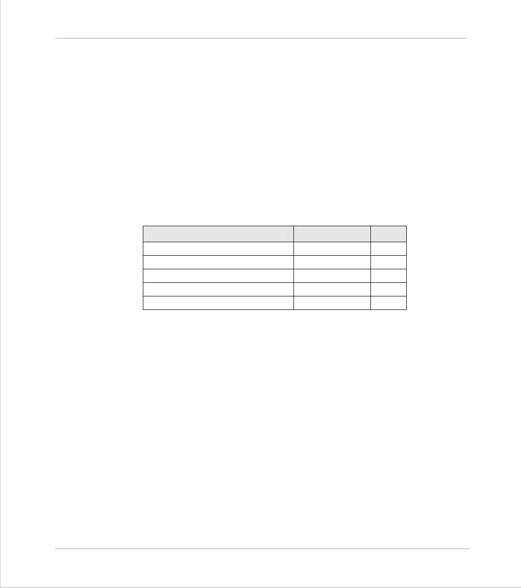
Default Settings:
A simple test program can be used to generate movement to and fro for exam-
ination of the motion profile generated on an oscilloscope. The oscilloscope
should be connected to the tacho or velocity output from the servo drive.
Example:
PRINT "Enter Axis Number ":INPUT VR(0)
BASE(VR(0))
SPEED=20000
ACCEL=200000
DECEL=200000
loop:
MOVE(1000)
WAIT IDLE
WA(100)
MOVE(-1000)
WAIT IDLE
WA(100)
GOTO loop
Gain Parameter Name Value
Proportional Gain
P_GAIN
1.0
Integral Gain
I_GAIN
0.0
Derivative Gain
D_GAIN
0.0
Output Velocity Gain
OV_GAIN
0.0
Velocity Feedforward Gain
VFF_GAIN
0.0