Motion Coordinator Technical Reference Manual
Fibre-Optic Network 11-5
General Description
Network Node Addressing
Nodes on the network are not given absolute addresses. Instead, when a message
is sent it is labelled with the address of a destination node which defines the
number of nodes along the ring from the sender that the message must travel.
The addresses are in the range 10, denoting a message for the next node along
the ring, to 24, denoting a message for the fifteenth node along the ring from the
sender.
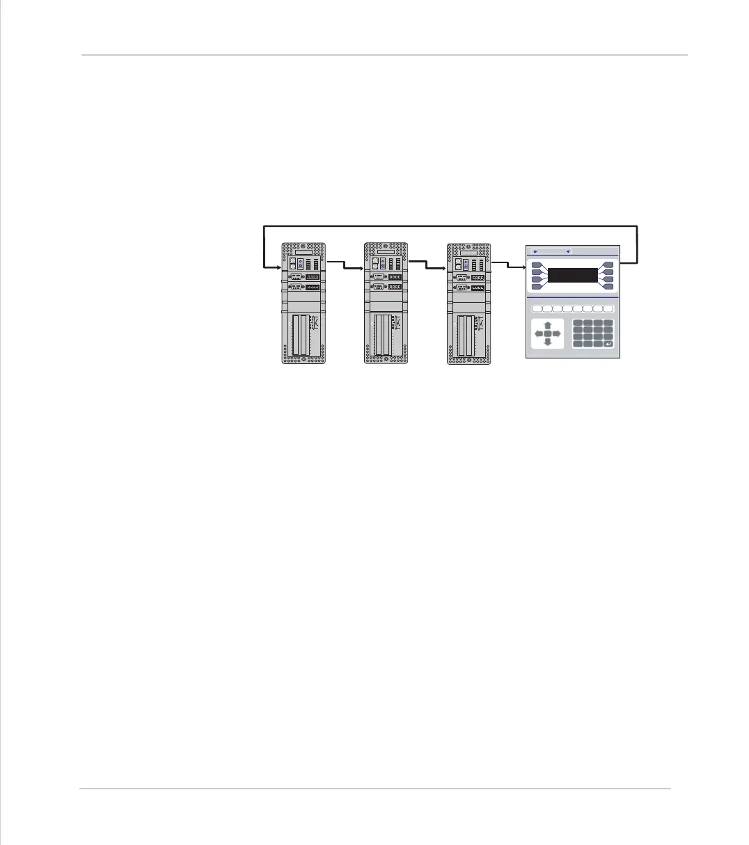
Node Addressing Example
The example above shows the destination node addresses for a network with
respect to the transmitting Motion Coordinator. If a message was sent with the
address 13 then the message would come back to the sender. Likewise if address
14 was used the message would completely traverse the ring once and finish up
at node #10. If address 18 was used then the message would go twice round the
ring and finish up at node #10.
ENCODER
V+ V- R
0v
5 4 3 2 1
9 8 7 6
ENCODER
V+ V- R
0v
5 4 3 2 1
9 8 7 6
IO8
IO9
IO10
IO11
IO12
IO13
IO14
IO15
I 0
I 1
I 2
I 3
I 4
I 5
I 6
I 7
24v
0v
Trio
8
9
10
11
12
13
14
15
0
OKNET
0
1
STATUS
1
2
3
4
5
6
7
7
4
1
-
8
5
2
0
9
6
3
.
Y
N
CLR
Trio Motion Technology
ENCODER
V+ V- R
0v
5 4 3 2 1
9 8 7 6
ENCODER
V+ V- R
0v
5 4 3 2 1
9 8 7 6
IO8
IO9
IO10
IO11
IO12
IO13
IO14
IO15
I 0
I 1
I 2
I 3
I 4
I 5
I 6
I 7
24v
0v
Trio
8
9
10
11
12
13
14
15
0
OKNET
0
1
STATUS
1
2
3
4
5
6
7
R
R
R
T
T
T
ENCODER
V+ V- R
0v
5 4 3 2 1
9 8 7 6
ENCODER
V+ V- R
0v
5 4 3 2 1
9 8 7 6
IO8
IO9
IO10
IO11
IO12
IO13
IO14
IO15
I 0
I 1
I 2
I 3
I 4
I 5
I 6
I 7
24v
0v
Trio
8
9
10
11
12
13
14
15
0
OKNET
0
1
STATUS
1
2
3
4
5
6
7
R
T
SEND #10 #11 #12