Motion Coordinator Technical Reference Manual
Communications Protocols 13-6
MODBUS RTU
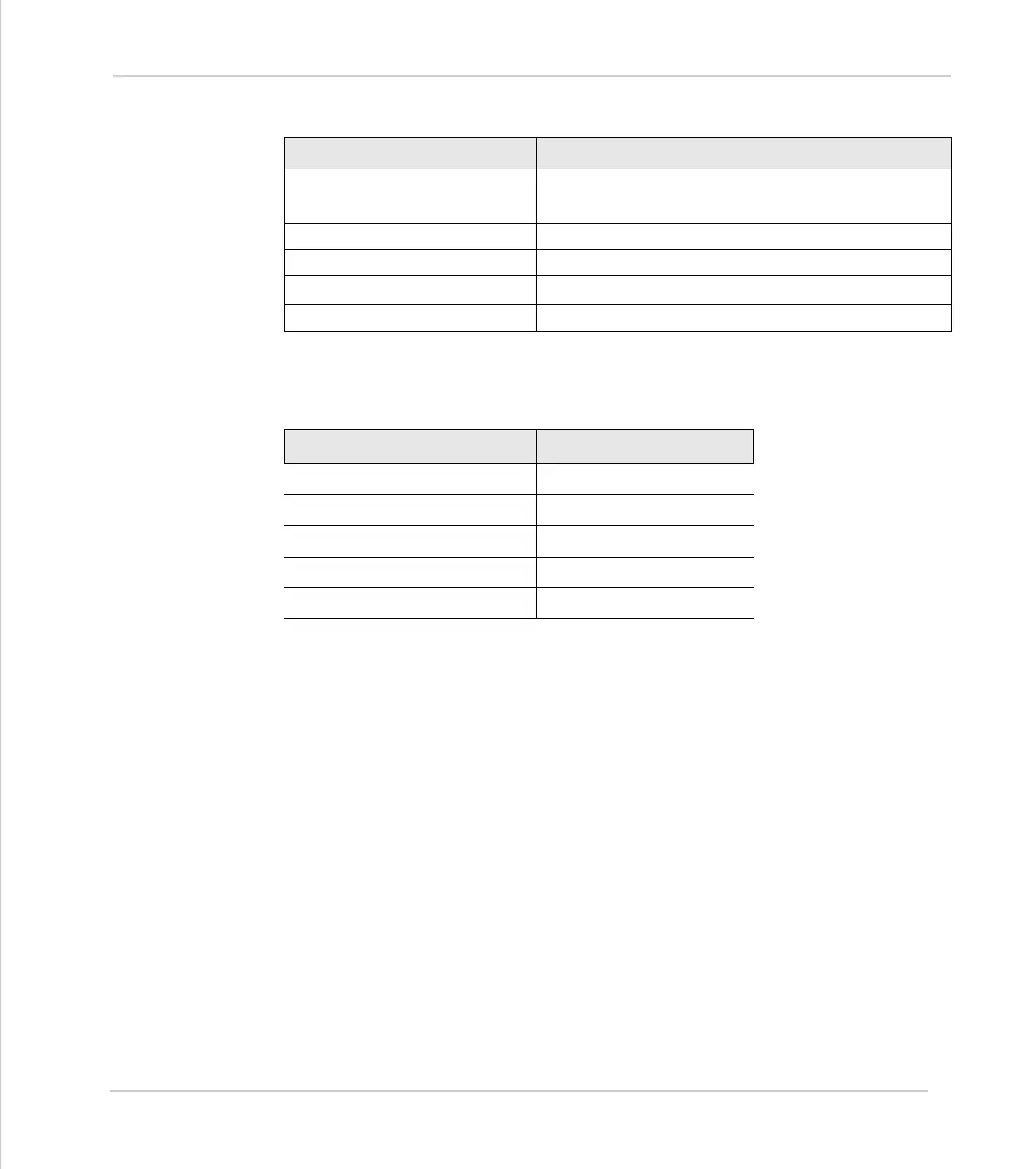
(16) Preset Multiple Registers
Notes
The following baud rate limitations should be observed when attaching a HMI
panel to the Motion Coordinator using Modbus.
Some HMI’s use the standard MODICON addressing for registers and I/O. If this is
the case, use the following mappings:
• Holding Registers 40001 + are mapped to VR(0) +
• Inputs 10001 to 10272 are mapped to IN(0) to IN(271) when the appropriate I/
O expansion is fitted.
• Output Coils 9 to 272 are mapped to OP(8,s) to OP(271,s) where s is the state
(ON or OFF)
Modbus Function Code 6
Mapped Trio Function Set VR() Global Variables: VR(addr)=data
1
……
VR(addr+n)=data
n
Starting Address Range 0 to 250
Number of Points Range 1 to 127
Data
1
to Data
n
-32768 to 32767 (16 bit signed)
Returned Data None
Motion Coordinator
Maximum Baud Rate
MC202
9600
Euro205
38400
MC206
38400
MC216
38400
MC224
38400