1
2018/02
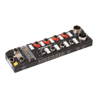
TBIP-L…-FDIO1-2IOL - Standard IO-Link
Part 3 – TBIP-L…-FDIO1-2IOL – Standards IO-Link channels
Table of Contents
1 About this User Manual 3
1.1 Documentation Concept 3
1.2 Target Groups of these Operating Instructions 3
1.3 Additional Documents 3
1.4 Explanation of Symbols Used 4
1.5 Manufacturer and Service 4
2 Properties of the IO-Link channels 5
2.1 Device structure 6
2.2 Power supply of the IO-Link ports 7
2.2.1 Class A/B supply 7
2.2.2 Safe shutdown of IOL2 (at C7) 7
2.3 Technical data 8
2.4 Connecting 9
2.5 Process Data of the IO-Link Master Channels 10
2.5.1 Process Image TBIP-L…-FDIO1-2IOL 10
2.5.2 Process Input Data – IO-Link Master Channels 11
2.5.3 Process Output Data – IO-Link Master Channels 13
2.6 Parameters 14
2.7 Adapting the Process Data Mapping 19
2.8 Diagnostics and Status 20
2.8.1 LED Displays Channel LEDs (C4 to C5) 20
2.8.2 Diagnostic Data 21
2.9 Using IO-Link and Turck Device DTMs 24
2.9.1 Topology Scan 24
3 IO-Link – Data Storage 25
3.1 Parameter "Data Storage Mode" = activated 26
3.2 Parameter "Data Storage Mode" = read in 27
3.3 Parameter "Data Storage Mode" = overwrite 28

 Loading...