Mounting
Hans Turck GmbH & Co. KG | T +49 208 4952-0 | F +49 208 4952-264 | more@turck.com | www.turck.com
28
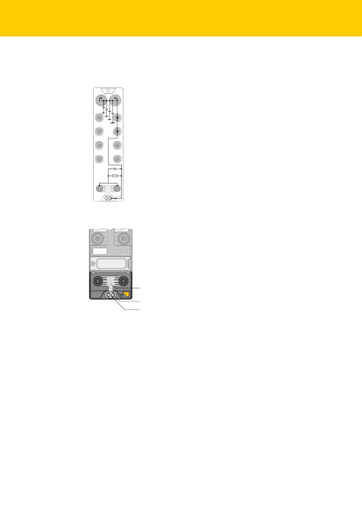
4.3 Grounding the Device
The grounding/shielding concept of the TBxx-devices allows the separate grounding of fieldbus-
and I/O-part
1 nF
2,2 MΩ
X1
C0
C1
C2
C3
P1
X2
C4
C5
C6
C7
P2
4 x 15 nF
Fig. 7: Equivalent circuit diagram, shielding con-
cept
Fig. 8: Grounding components
The metal clamp (1) at the M12-connectors for the fieldbus con
nection (P1, P2) connects the shield
of the fieldbus lines.
The metal ring (2) is situated under the metal cl
amp an connects the functional earth of the
7/8'' connectors (pin 3) for the voltage supply to th
e FE of the M12-connectors (pin 5) for the con-
nection of the sensors and actuators.
By mounting the module onto a mounting plate through the mounting
hole, the mounting screw
is used to realize the connection to the reference potential of the installation.
1 metal clamp
2 Metal ring
3Mounting screw

 Loading...
