Properties of the IO-Link channels
Hans Turck GmbH & Co. KG | T +49 208 4952-0 | F +49 208 4952-264 | more@turck.com | www.turck.com
6
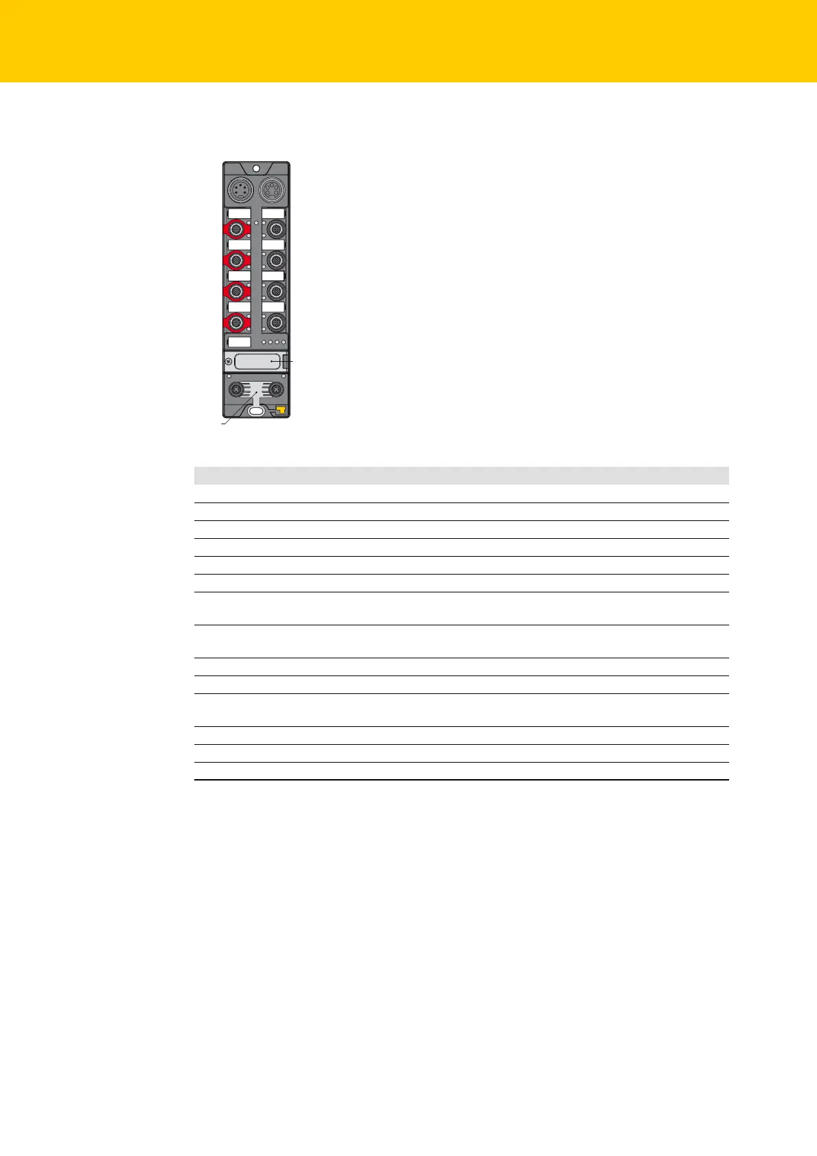
2.1 Device structure
The IO-Link channels are designed as follows:
The IO-Link channels at pin 4 at connectors C6 and C7 can be parameterized independently and
can optionally be operated in IO-Link mode (IOL) or in standard I/O mode (SIO/DI mode).
The universal channels at pin 2 of connectors C6 and C7 are designed as DXP channels and can
thus be used as in- or output.
Fig. 1: Device structure
Meaning
X1 Power IN
X2 Power OUT
C0 FDI0/1, safety-related input
C1 FDI2/3, safety-related input
C2 FDX4/5, safety-related in-/output
C3 FDX6/7, safety-related in-/output
C4 DXP8/9, standard in-/outputs
(safe shutdown via FSO 0 possible)
C5 DXP10/11, standard in-/outputs
(safe shutdown via FSO 0 possible)
C6 IOL, IO-Link port1
C7 IOL, IO-Link port 2 (safe shutdown via FSO 1 possible)
IP address Rotary coding switch for address setting (last byte of the IP address for the safe func-
tion unit)
P1 Ethernet 1
P2 Ethernet 2
FE Functional earth
C4
C5
C6
C7
C0
C1
C2
C3
X2X1
P2
P1
FE
IP Address

 Loading...
