Properties of the IO-Link channels
Hans Turck GmbH & Co. KG | T +49 208 4952-0 | F +49 208 4952-264 | more@turck.com | www.turck.com
14
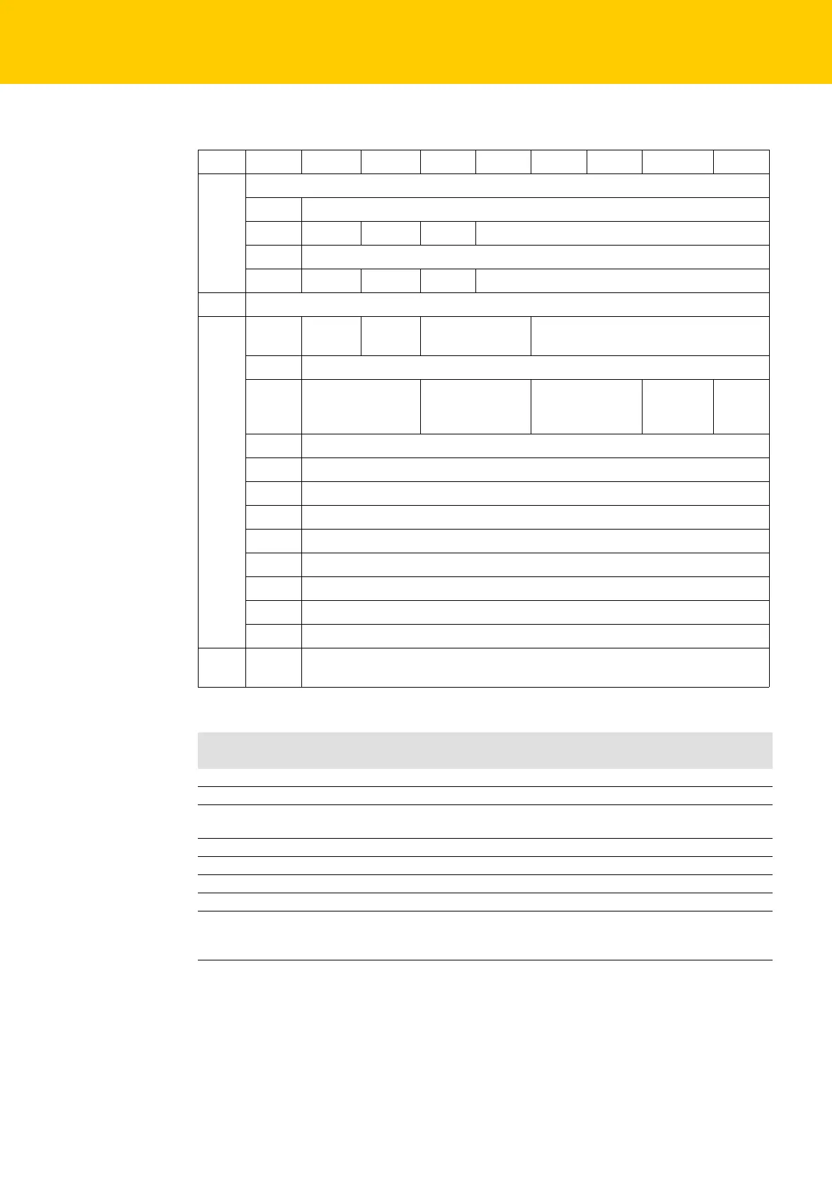
2.6 Parameters
Byte Bit 7 Bit 6 Bit 5 Bit 4 Bit 3 Bit 2 Bit 1 Bit 0
Basic
0-
1 SRO15 - SRO13 -
2-
3 EN DO15 - EN DO14 -
IO-Link
Port 1 4 GSD Quick
Start-Up
Data storage mode Mode
5 Cycle time
6 Mapping process
output data
Mapping process
input data
Diagnostics
deactivate web
server
Process
input data
invalid
Revision
7 to 11 reserved
12 Vendor ID (LSB)
13 Vendor ID (MSB)
14 Device ID (LSB)
15 Device ID
16 Device ID
17 Device ID (MSB)
18 reserved
19 reserved
Port 2 20 to
35
Assignment similar to port 1 (byte 4 to 19)
Name Meaning
Value
SRO Manual output reset after overcurrent
0 0 = no A The output switches on automatically after an overload.
1 1 = yes The output is manually switched-off after an overload until a new
set-command is given (rise and fall).
EN DO Activate output
0 0 = no A The output at pin 2 is deactivated.
1 1 = yes The output at pin 2 is activated.
Mode
0000 IO-Link without
validation A
Pin 4 is operated in IO-Link mode.
The master does not check if the connected device matches the
configured one.

 Loading...
