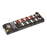
Properties of the IO-Link channels
Hans Turck GmbH & Co. KG | T +49 208 4952-0 | F +49 208 4952-264 | more@turck.com | www.turck.com
20
2.8 Diagnostics and Status
2.8.1 LED Displays Channel LEDs (C4 to C5)
LED LED
GREEN
LED
RED
Meaning Remedy
IO-Link
C6, LED 12
and
C7, LED 14
Channel in IO-Link-mode
off off No IO-Link communication, diag-
nostics deactivated
– connect an IO-Link device
– Parameterize the channel as
DI if necessary.
– wire break in IO-Link cable
possible
blink-
ing
off IO-Link communication active,
valid process data
off blink-
ing
IO-Link communication active and
module error, invalid process data
– No input data received from
the connected device (only
valid for devices with an input
data length > 0),
– No reaction from the con-
nected device to the sending
of output data (only valid for
devices with an output data
length > 0),
– connected device sends an
error: "process data invalid".
see also:
Start-up Problems – Fre-
quently Failure Causes (page
38)
off on No IO-Link communication
and/or module error,
invalid process data
Channel in DI-mode
off off Input active
on off Input signal active
DXP
C6, LED 13
and
C7, LED 15
off off -
on off In-/ output signal active
off on Short circuit at output of the
respective channel

 Loading...