35
2018/02
TBPN-L1-FDIO1-2IOL- Safe I/O
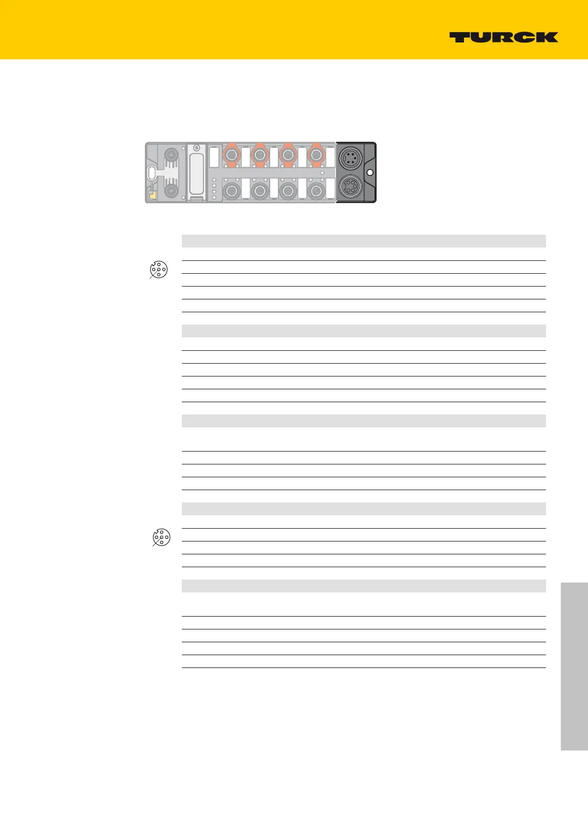
5.4 Connecting Sensors and Actuators
The device has eight 5-pin M12 connectors for connecting digital sensors and actuators. The maxi-
mum tightening torque is 0.8 Nm.
wv
1
2
3
4
1 RD = 24 VDC V2
2 GN = 24 VDC V1
3 WH = GND V1
4 BK = GND V2
1
2
3
4
X1 X2
Connect the sensors and actuators to the device according to the pin assignment shown below.
Safety-related inputs (FDI) – C0 and C1
1 VAUX1/T1 Sensor supply/ test pulse 1
2 FDI (T2) Digital input 1
3 GND (V1) Ground V1
4 FDI (T1) Digital input 2
5 T2 Test pulse 2
FE
Connected to the thread of the M12 connector
Safety-related in-/outputs (FDX) – C2 and C3
1 VAUX1/T1 Sensor supply/ test pulse 1
2 FDO-/FDI (T2) Digital output/ digital input 1 (M)
3 GND
V1
Ground V1
4 FDO+/FDI (T1) Digital output/ digital input 2 (P)
5 T2 Test pulse 2
6 FE
Connected to the thread of the M12 connector
Universal standard I/Os – C4 and C5
1 FSO 0 Sensor supply (internal safe shutdown possible)Block dia-
gram (page 15)
2 DI/DO digital in-/output
3 GND (V1) Ground V1
4 DI/DO digital in-/output
5 FE Functional earth
IO-Link-port 1 – C6
1 VAUX1 Class B supply
2 DI/DO digital in-/output
3 GND (V1) Ground V1
4 C/Q IO-Link
5 GND (V1)
Functional earth
IO-Link-port 2 – C7
1 FSO 1 Class B supply (internal safe shutdown possible)
see
Block diagram (page 15)
2 DI/DO digital in-/output
3 GND (V1) Ground V1
4 C/Q IO-Link
5 GND (V1) Functional earth
We recommend pre-assembled 5-pole sensor cables. Suitable cables can be found on
www.turck.de under "Products Fi
eldbus technology Accessories".

 Loading...
