33
2018/02
TBPN-L1-FDIO1-2IOL- Safe I/O
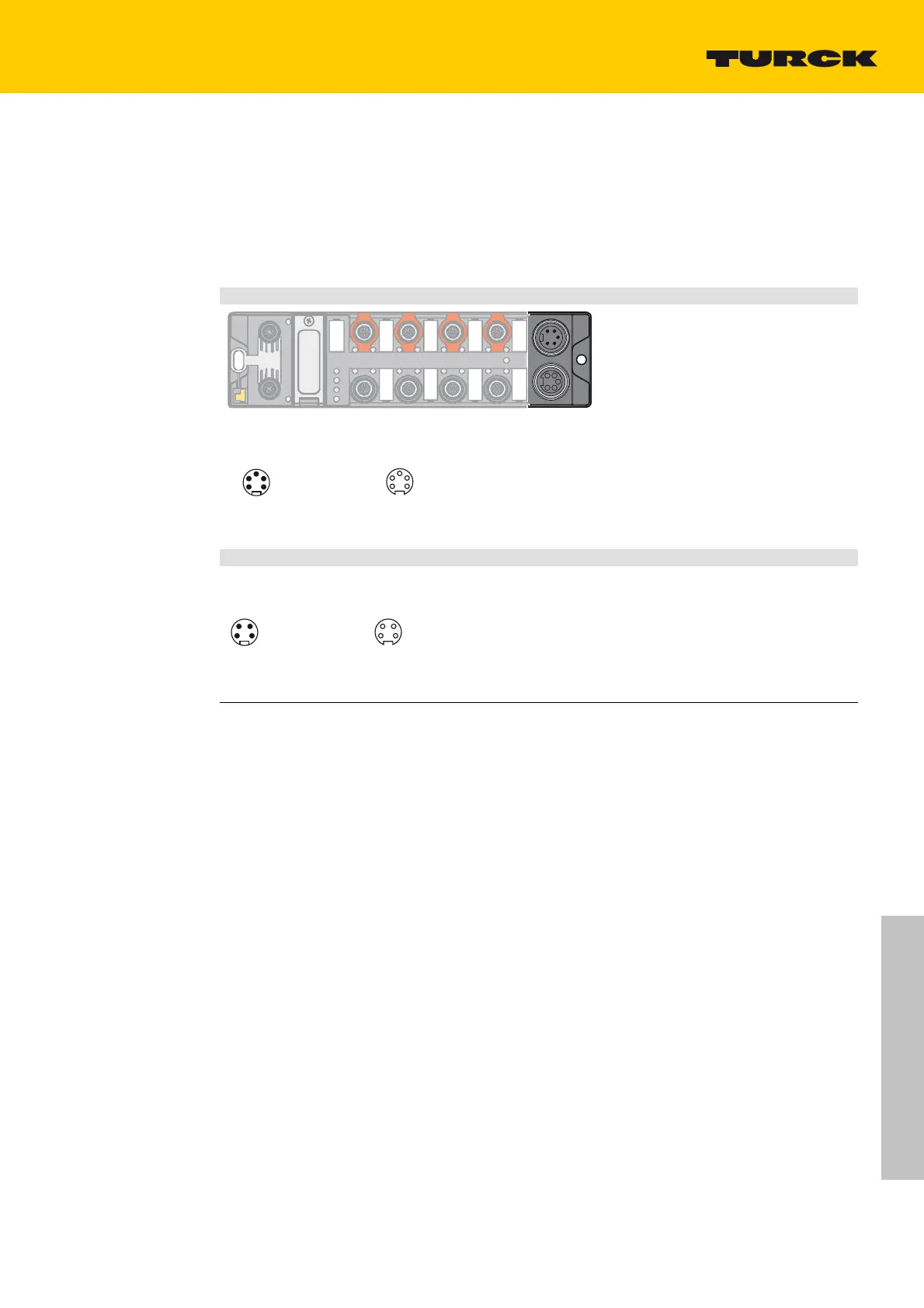
5.3 Connecting the Power Supply
For the connection to the power supply and the feeding through of the power, the device has two
5-pin 7/8" connectors.
The power supply connectors are designed as 4-pole (TBEN-L4) or 5-pole (TBEN-L5) 7/8" connectors.
V1 an
d V2 are galvanically isolated. The maximum tightening torque is 0.8 Nm.
Connect the device to the voltage
supply according to the pin assignment below.
Supply voltage 7/8“, 5-pole
wv
1
2
3
4
1 RD = 24 VDC V2
2 GN = 24 VDC V1
3 WH = GND V1
4 BK = GND V2
1
2
3
4
X1 X2
1 BK = V2 (–)
2 BU = V1 (–)
3 GNYE = FE
4 BN = V1 (+)
5 WH = V2 (+)
3
4
5
2
1
wv
3
4
5
2
1
X1 X2
X1 = voltage IN
X2 = voltage OUT for supplying the next node
V1 = supply voltage 1 (incl. supply of electronics)
V2 = supply voltage 2 (not used in the device, only looped
thro
ugh)
Supply voltage 7/8“, 4-pole
wv
1
2
3
4
1 RD = 24 VDC V2
2 GN = 24 VDC V1
3 WH = GND V1
4 BK = GND V2
1
2
3
4
X1 X2
X1 = voltage IN
X2 = voltage OUT for supplying the next node
V1 = supply voltage 1 (incl. supply of electronics)
V2 = supply voltage 2 (not used in the device, only looped
thro
ugh)
We recommend the use of pre-assembled 5-pole power supply cables,
Turck type 52 (z.B. RKM52-1-RSM52). Suitable cables c
an be found on www.turck.de under "Prod-
ucts Fieldbus
technology Accessories".

 Loading...
