Configuring with Turck Safety Configurator and Rockwell Studio 5000
Hans Turck GmbH & Co. KG | T +49 208 4952-0 | F +49 208 4952-264 | more@turck.com | www.turck.com
54
8.1.10 Customizing the Configuration
The standard configuration in the Turck Safety Configurator can be customized in order to meet the
requirements of different applications.
Customizing a Standard Application (Preliminary Considerations)
1 What is needed?
Definition of amount and type of the required in- and outputs
Which components are used for the safety function:
– electromechanical components
– electric components
– dual channel switching
– antivalent switching
– components with semiconductor OSSD output
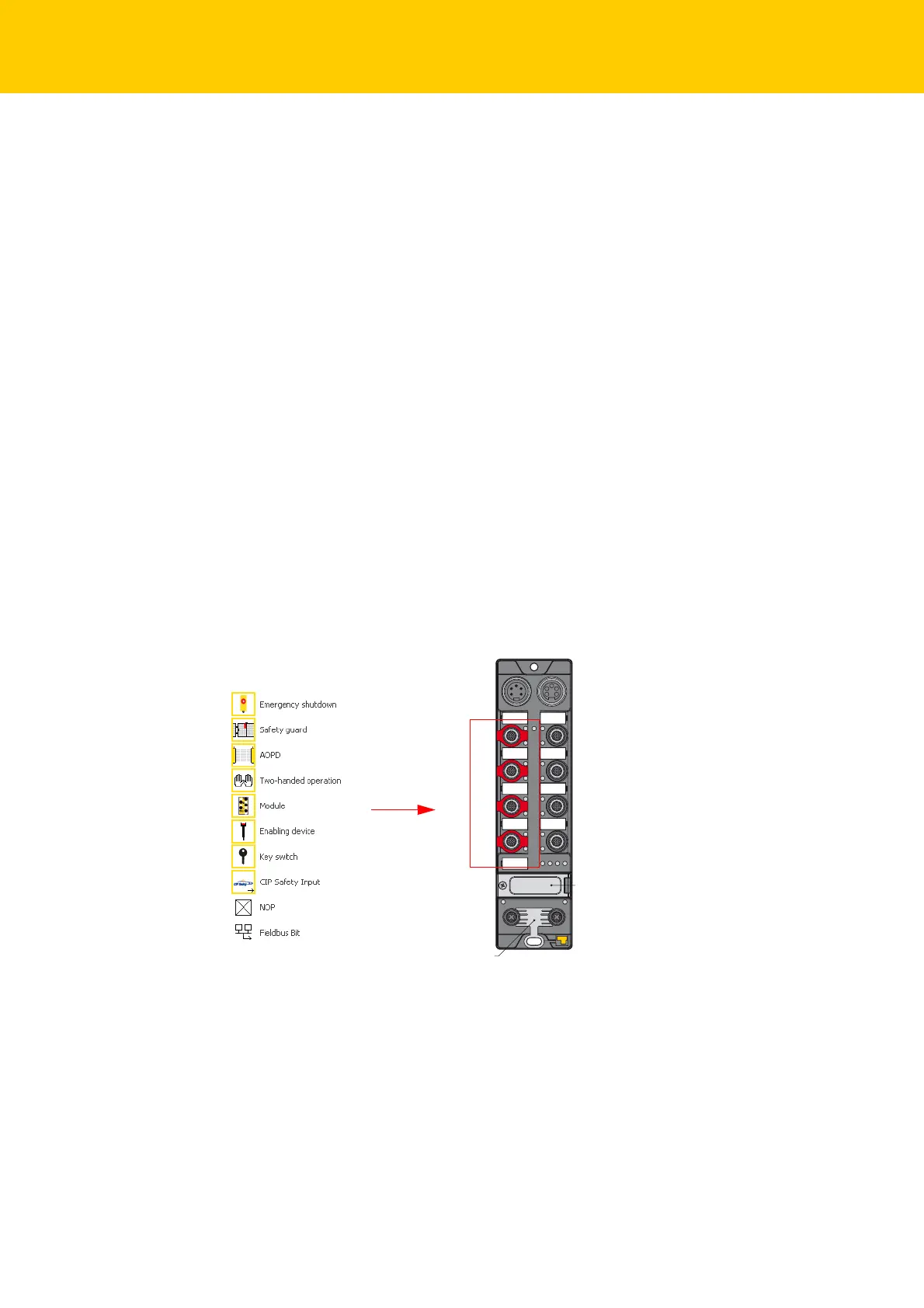
2 Where will the components be placed?
All red marked M12-connectors on the safety side (le
ft side) of the TBIP-L…-FDIO1-2IOL are
designed for connecting safety components.
In the standard configuration, the two lower M12-conn
ectors (C2 and C3) are configured as dual
channel SIL3-outputs. However, depending on the application, they can be used as SIL3-inputs. In
total, up to four 2- channel safety related SIL3-inputs can be connected to the device.
Possible input configurations:
C4
C5
C6
C7
C0
C1
C2
C3
X2X1
P2P1
FE
IP A
ddress
Fig. 29: Input configurations

 Loading...
