EasyManua.ls Logo

turck TBIP-L...-FDIO1-2IOL Series TBIP-L4-FDIO1-2IOL User Manual

turck TBIP-L...-FDIO1-2IOL Series
TBIP-L4-FDIO1-2IOL
165 pages
To Next Page IconTo Next Page
To Previous Page IconTo Previous Page
Page #151 background imageLoading...
Page #151 background image
25
V01.0| 2017/04
TBPN-L1-FDIO1-2IOL - Standard IO-Link
3 IO-Link – Data Storage
Data storage enables a user to change an IO-Link device when maintenance is required without any
configuration or parameterization.
The IO-Link master, as well as the IO-link device, sto
re the device parameters. The data storage
mechanism serves for synchronizing these different data storage buffers.
In case of a device change, the master writes the stored device parameters to the new device. The
applicatio
n can be re-started without any further intervention using a configuration tool or similar.
In the IO-Link master, the data stor
age mode can be set using the parameter "data storage mode"
(see Parameters (page 14)).
data storage mode
00 = activated ( s. page 26)
01 = overwrite ( s. page 27)
10 = read in ( s. page 28)
11 = deactivated, clear ( s. page 28).
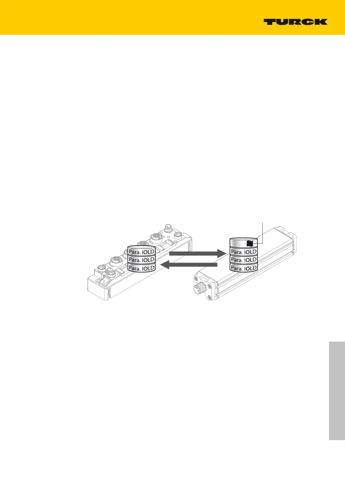
IO-Link-Master
(IOLM)
IO-Link-Device
(IOLD)
DS_UPLOAD_FLAG
Para. IOLD = parameter data of the IO-Link device
Fig. 3: General principle of the data storage mechanism
A change of parameters in the device is indica
ted by the status of the DS_UPLOAD_FLAG bit:
DS_UPLOAD_FLAG:
0 = no changes in the device's parameter
set
1 = changes in the device's parameter set (e.
g. via DTM, at the device, etc.)

Table of Contents

Question and Answer IconNeed help?

Do you have a question about the turck TBIP-L...-FDIO1-2IOL Series TBIP-L4-FDIO1-2IOL and is the answer not in the manual?

turck TBIP-L...-FDIO1-2IOL Series TBIP-L4-FDIO1-2IOL Specifications

General IconGeneral
Product CategoryI/O Systems
SeriesTBIP-L...-FDIO1-2IOL
ModelTBIP-L4-FDIO1-2IOL
IO-Link Ports1
Protection ClassIP67
Operating Voltage24 V DC
Connection TechnologyM12
Communication InterfaceIO-Link
Power Supply24 V DC

Summary

About this user manual

Documentation concept

Describes the manual's structure, including parts and chapters covered.

Target Groups of these Operating Instructions

Identifies qualified and trained personnel as the intended audience for this manual.

Manufacturer and Service

Provides contact information for Turck GmbH & Co. KG and support resources.

For Your Safety

Intended Use

Defines the safe hybrid safety module's purpose and application in safety instrumented systems.

General Safety Instructions

Provides essential safety guidelines for device operation, risk assessment, and installation.

Legal Requirements

States that manufacturers and operators must observe relevant directives and standards.

Product description

Device Overview

Presents the TBIP-L -FDIO1-2IOL module, its features, and available versions.

Device structure

Details the physical structure of the device, including connectors and components.

Technical Data

Provides general technical specifications including supply voltage, connectors, and Ethernet properties.

Safe I/O channels

Describes the two 2-channel safe digital inputs (FDI) and two safe connectors (FDX) configurable as in/out.

Configuration Memory

Explains the pluggable memory stick for storing safety configurations and device exchange.

Mounting

Mounting the Device

Provides instructions and torque specifications for physically mounting the device.

Grounding the Device

Explains the grounding and shielding concept for fieldbus and I/O parts.

Connecting

Connecting the M12 Connectors

Guides on connecting cables to M12 connectors using a torque screwdriver.

Connecting the Devices to Ethernet

Describes connecting the device to Ethernet via M12 connectors and provides pin assignments.

Connecting the Power Supply

Explains connecting the power supply using 7/8" connectors and provides pin assignments.

Setting IP Addresses

Address setting via Rotary Coding Switches

Explains how to set IP addresses using rotary coding switches and their meanings.

Setting the IP Address via the Web Server

Details how to configure IP addresses using the device's web server.

Commissioning

Initial Commissioning

Outlines the steps for initial commissioning, including mounting, electrical installation, and IP address setting.

Configuring with Turck Safety Configurator and Rockwell Studio 5000

Configuring the device with Turck Safety Configurator

Details the process of configuring the device using the Turck Safety Configurator software.

Configuring the device at CIP Safety (Rockwell Studio 5000)

Details on configuring the device within Rockwell Studio 5000 for CIP Safety.

Assigning the Safety Network Number

Details how to assign a Safety Network Number to uniquely identify the safety module.

Operating

LED Displays

Describes the meaning and remedies for Module Status (MS) and Network Status (NS) LEDs.

Process Input Data

Provides an overview of the structured process input data for the entire module.

Restarting after device exchange or modification

Changing a TBIP-L -FDIO1-2IOL

Outlines the process for replacing a device.

Maintenance, repair, decommissioning and disposal

Maintenance

States the device is maintenance-free for 20 years and specifies testing for used cables and sensors.

Repair

States that the device is not repairable and must be returned to Turck for errors.

Glossary of terms

PL

Performance Level, a measure of safety function dependability.

SIL

Safety Integrity Level, a discrete level for safety-related systems.

Related product manuals