iSTAR eX Features
iSTAR eX Installation and Configuration Guide 1–7
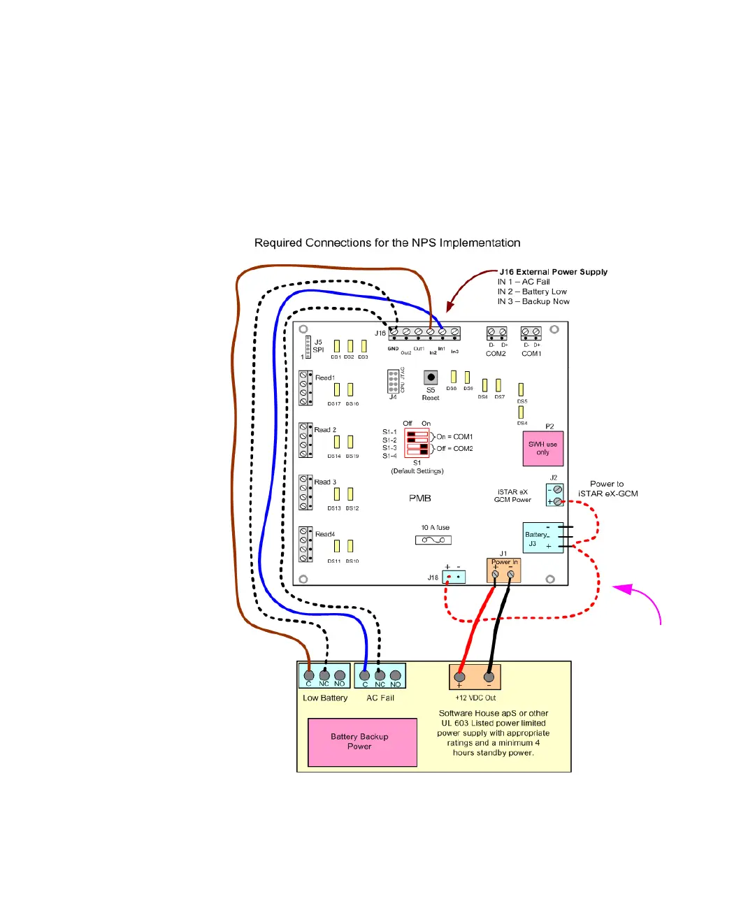
Figure 1-2 illustrates how to wire the NPS version. Connect the following:
+12 VDC and Ground from External Power Supply to PMB J1. Observe polarity.
AC Fail to J16 - IN 1. Wire C and NC pins. There is no polarity.
Low Battery to J16 - IN 2. Wire C and NC pins. There is no polarity.
Verify Jumper from J2(+) to J3(+) to J18(+)
Figure 1-2: iSTAR eX NPS Power Connections
Note: The jumper from J2
to J3 to J18 is factory installed
on the NPS model.