Chapter 7: Field Service Components 00.053.204, Revision A SonixTouch Q+ Service Manual
7-18
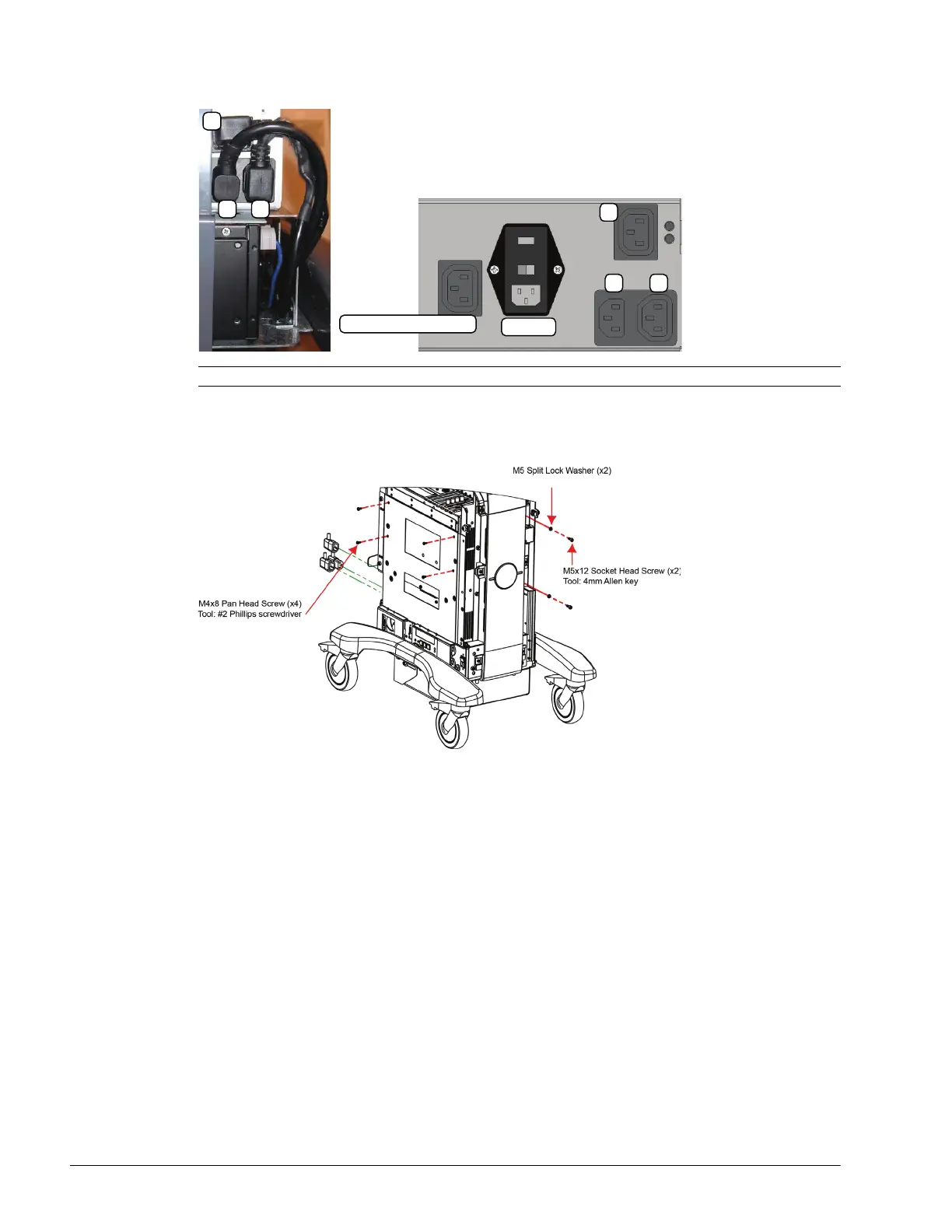
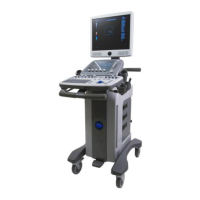
6. Disconnect the three (bottom left rear) power cables connected to the modulo: LCD display power cable (1),
UPS input power cable (2) and UPS output power cable (3).
7. Using the 4mm Allen key, undo the two screws and washers securing the modulo to the front of the system
frame.
8. Using the #2 Phillips screwdriver, undo the four screws securing the modulo to the side of the system frame.
9. Pull the modulo out of the system frame, then lift it clear.
Note: The LCD display power cable (1) is color coded with green tape.
System Power Connection
EMI Filter
1
2 3
1
2 3