Chapter 8 ____________________________________________________________ Technical Data
VAISALA______________________________________________________________________ 241
Figure 126 on page 240 provides a schematic wiring diagram for the dual
RS-485 connection, a dual 2-wire connection utilizing both channels. The
correct jumper settings for the channel B are listed in Table 72 on page
242. The jumpers are located on the module as illustrated in Figure 127
below.
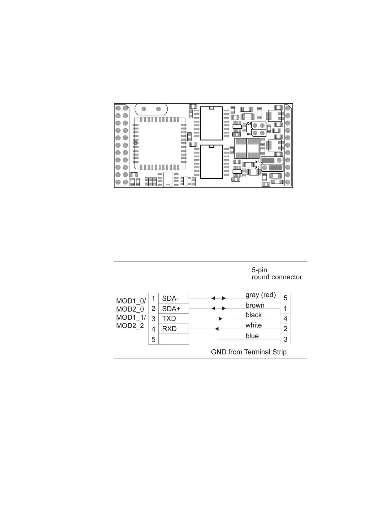
0903-024
Figure 127 RS-232 Jumper Settings
Figure 128 below provides a schematic wiring diagram for the
combination of the RS-485 and RS-232 connection. Jumpers X3 and X6
are used to select between the RS-485 and RS-232 modes for channel B.
The correct jumper settings for channel B are listed in Table 72 on page
242.
1006-102
Figure 128 Dual RS-485 Wiring Diagram for RS-485 and RS-232