User's Guide ______________________________________________________________________
242 _________________________________________________________________ M211296EN-A
Table 72 Jumper Settings for DSI486-B
Jumper Connected
Pins
Function
1-2 Channel B RS-232 mode X3
2-3 Channel B RS-485 mode (default)
1-2 Channel B RS-485 mode (default) X6
2-3 Channel B RS-232 mode
X4 1-2 Channel A RS-485 line terminating resistor
active
X5 1-2 Channel B RS-485 line terming resistor active.
Do not use in RS-232 mode
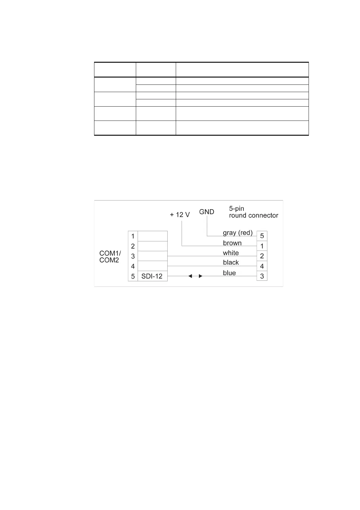
The dual RS-485 module also provides an SDI-12 connection. The SDI-
12 line uses one wire for data and is limited to the maximum length of
60 meters. Figure 129 below provides a schematic wiring diagram for the
SDI-12 connection and the 12 VDC power supply for a sensor. The
jumper settings should be as shown in Figure 127 on page 241.
1006-103
Figure 129 Dual RS-485 Wiring Diagram for SDI-12 and 12 VDC
Power Supply
Simultaneously with the SDI-12, you can connect channels A and B in
the 2-wire RS-485 mode.