NOTE: Use port DP1 for the HMI system display.
DO ports
The monitoring unit provides two digital output ports DO1 and DO2 as shown in Monitoring Unit Front Panel on page14 . The
following table describes the parameters for the digital output ports.
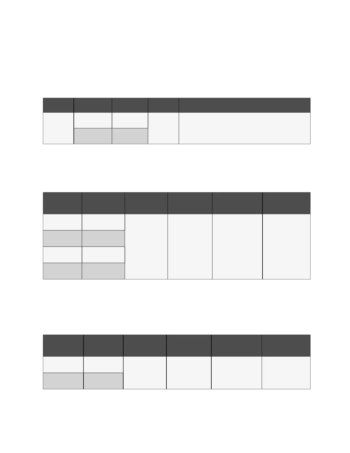
Port Output Range Port Usage
DO1/DO2
Voltage 9V to 12.5V
RJ45
• DO output, can be connected to the alarm indicator.
• The maximum total power of the two ports can support
2.4W.
• Support short circuit protection.
Total current ≤0.2A
Table 2.20 DO Port Parameters
DI ports
The monitoring unit provides four digital input ports as shown in Monitoring Unit Rear Panel on page14 . The following table
describes the parameters for the DI ports.
Silk Screen
Printing
Definition
Rated Output
Voltage
Output Current
(Total)
Max Output Power
(Total)
Port Overload
Protection
DI1
Port of magnetic door
switch 1
9V~12.5V <0.16A 1.92W
Support overload
protection
DI2
Port of magnetic door
switch 2
Smoke 1
Port of smoke
detector 1
Smoke 2
Port of smoke
detector 2
Table 2.21 DI Port Electrical Parameters
Sensor port
The monitoring unit provides two sensor groups with each each group having two sensor ports as shown in Monitoring Unit
Rear Panel on page14 . Each port has an RJ45 interface. The following table describes the electrical parameters for the sensor
ports.
SilkScreen
Printing
Definition
Rated Output
Voltage
Output Current
(Total)
Max Output Power
(Total)
Port Overload
Protection
Sensor 1
Port of 1st chain of
sensors
9 VDC to 12.5 VDC <0.36A 4.32W
Support overload
protection
Sensor 2
Port of 2nd chain of
sensors
Table 2.22 Sensor Port Electrical Parameters
2 Getting Started Proprietary and Confidential ©2024 Vertiv Group Corp. 17
Vertiv™ SmartRow™ 2 Infrastructure Solution User Guide