E-2 Videojet DataFlex 6530 Service Manual - Rev AA
E.1.6 Physical Installation
When only two Videojet DataFlex 6530 printers (one Master, one Slave) are required and there is
no requirement to connect the Master/Slave group to an external network, a two printer
interconnection cable may be used to connect directly between the Ethernet ports of the two
printers.
All other cables (e.g. I/O cable) must be connected in the same way as the standalone printers.
When more than two printers are to be connected together or connection to a network is
required, the ethernet connections can either be daisy chained between printers or a printer
connection box complete with ethernet patch cables can be used.
The Connection Box allows up to four Videojet DataFlex 6530 printers (one Master and three
Slaves) to be connected together, allowing them to share common encoder and print signals as
well as providing ethernet connectivity via the integral network switch (hub).
In addition to this, the connection box also allows the group of printers to be connected to a
wider Ethernet network.
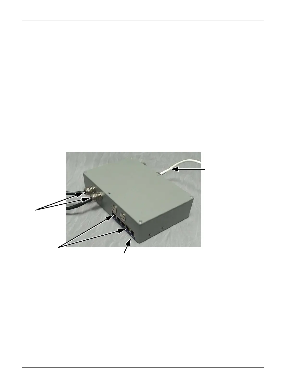
Figure E-1 shows a two printer connection box, indicating the five port connections for the
network switch, integral I/O cables (2 numbers) and encoder lead.
1
1. Encoder Lead
2. Network Connector
3. Ethernet Ports
4. Integral I/O Cables
Figure E-1: Printer Connection Box
4
3
2