Videojet DataFlex 6530 Service Manual - Rev AA 4-1
Section 4 Installation
Introduction
This chapter contains the following topics:
• Unpacking the Standard Printer
• Installing the Printer
• Mounting Considerations
• Installing the Ribbon in the Cassette
• Switching the Power On
• Switching the Power On
• Switching the Power On
• Understanding Printhead LEDs
• Configuring the Printer
• Working with the Configurable Inputs and Outputs
• Setting the End of Reel Detection
• Working with Print Allocations
4.1 Unpacking the Standard Printer
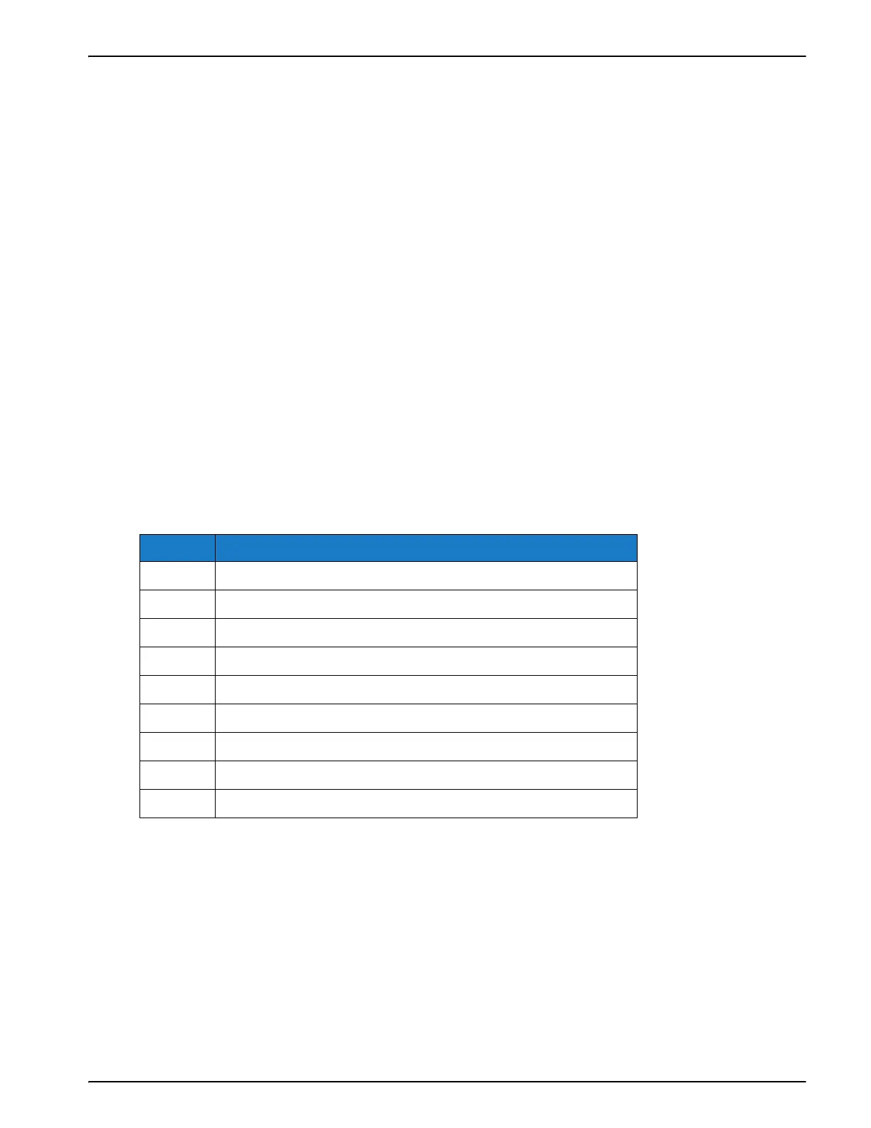
Inspect the kit for any damage carefully. Refer the list of parts in Table 4-1. If any item is damaged
or missing, call Videojet customer service.
4.2 Installing the Printer
Ensure that the following services are available where the printer is being installed:
• Power: 100 -240 VAC, 50/60 Hz, 1.56 A
• Print signal: This is the signal that triggers the printing operation and can either be a:
- PLC signal
- 24 V DC, PNP registration photocell
- 24 V DC, PNP proximity switch detecting a cam timing point
No. Printer Parts
1 Printer and Cassette
2 GUI Cable (3M)
3CLARiTY HMI Display
4PSU
5Power Cable
6 Low Profile Cable Assembly
7 CLARiTY Configuration Manager/Documentation USB
9 Wall Mount Bracketry and Screws
10 QA Documentation and CE Certificate
Table 4-1: Printer Configuration Parts List