Videojet DataFlex 6530 Service Manual - Rev AA 3-13
Main Parts
3.2.4 Data Communication
All external data communication to the printer are connected through the PSU. It contains the
following communication ports:
• RS232 Serial Communications Port (9-pin Male D-type Connector)
• Ethernet 10baseT/100baseTX High Speed Network Port (RJ45 Connector)
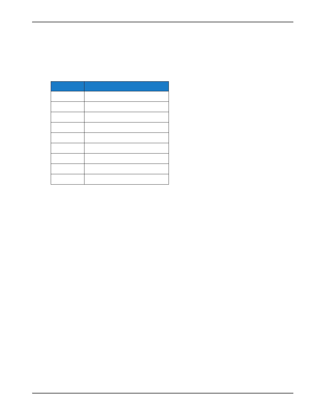
Table 3-3 lists the connections to the RS232 Serial Communications Port
The printer is primarily designed to communicate with the CLARICOM Package Coding
Management Software, such as the CLARiSOFT Image Design Software and CLARiNET Coder
Networking Software (supplied separately). CLARiTY is supplied with some default images
installed in its database memory.
CLARiTY can be configured to work in one of the following modes:
•Standalone Mode
Download images to CLARiTY using a standard PC null-modem cable (twisted 9-pin
D-type, female to female) connected between PC COM1 port and CLARiTY RS232 port
(cable supplied separately), using CLARiSOFT.
•Network Mode
Create images on a PC using CLARiSOFT.
Download to CLARiTY using the Ethernet TCP/IP network and CLARiNET network
software.
Images (Jobs) can be requested from the CLARiTY panel or can be selected and
downloaded from any networked PC workstation that is running CLARiNET.
Pin Purpose
1 Data Carrier Detect (DCD)
2 Receive Data (Rx)
3 Transmit Data (Tx)
4 Data Terminal Ready (DTR)
5Ground
6 Data Set Ready (DSR)
7 Request To Send (RTS)
8 Clear To Send (CTS)
9Ring Indicator (RI)
Table 3-3: RS232 Serial Communications Port Connections