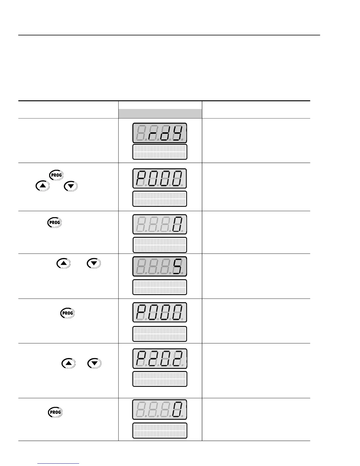
Inverter is ready to be operated
Enables the access to change
parameters content. With the factory
default programming [P200 = 1
(PasswordActive)],P000 must be set
to 5 to allow parameters changes
Enter the programmingmode
Password value (factory default = 5)
Exit the programming mode
Type of Control Selection:
Enter the programmingmode
Press the key to enter the
to set the password value
Press the key to save the
programmed value and exit the
Press the key to enter the
In order to get a good steady-state speed regulation, the slip frequency is
calculatedfrom theestimated load torque value(whichusesthe motor nameplate
The following sequence is valid for Connection#1 (refer toitem 3.2.7). The inver-
ter should havebeen alreadyinstalled and powered up according to instructions
in chapter 3 and item 5.2.
 Loading...


