CHAPTER 6 - DETAILED PARAMETER DESCRIPTION
DC Link Voltage (Ud) (P004)
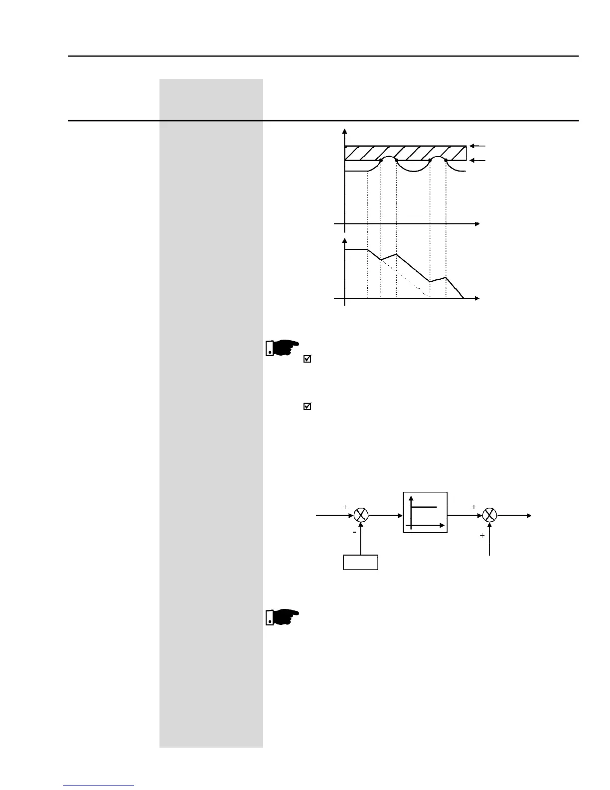
- Deceleration curve with DC Link voltage limitation (regulation)
The factory setting is at maximum (Link regulation is
deactivated). To activate this regulation, we recommend to set
If even after this setting the inverter is still disabled due to
overvoltage(E01)duringtheloadacceleration,increasethevalue
of the Parameter P152 gradually, or increase the deceleration
ramp time (P101 and/or P103). The inverter will not decelerate,
if the supplyline is permanently under overvoltageUd > P151).
In this case reduce the line voltage or increment P151.
- Voltage regulation block diagram of the DC Link
For large motors it’s recommended the use of the ramp holding


 To Next Page