CHAPTER 6 - DETAILED PARAMETER DESCRIPTION
Used to protect motor and inverter against timed overload (Ixt - E05).
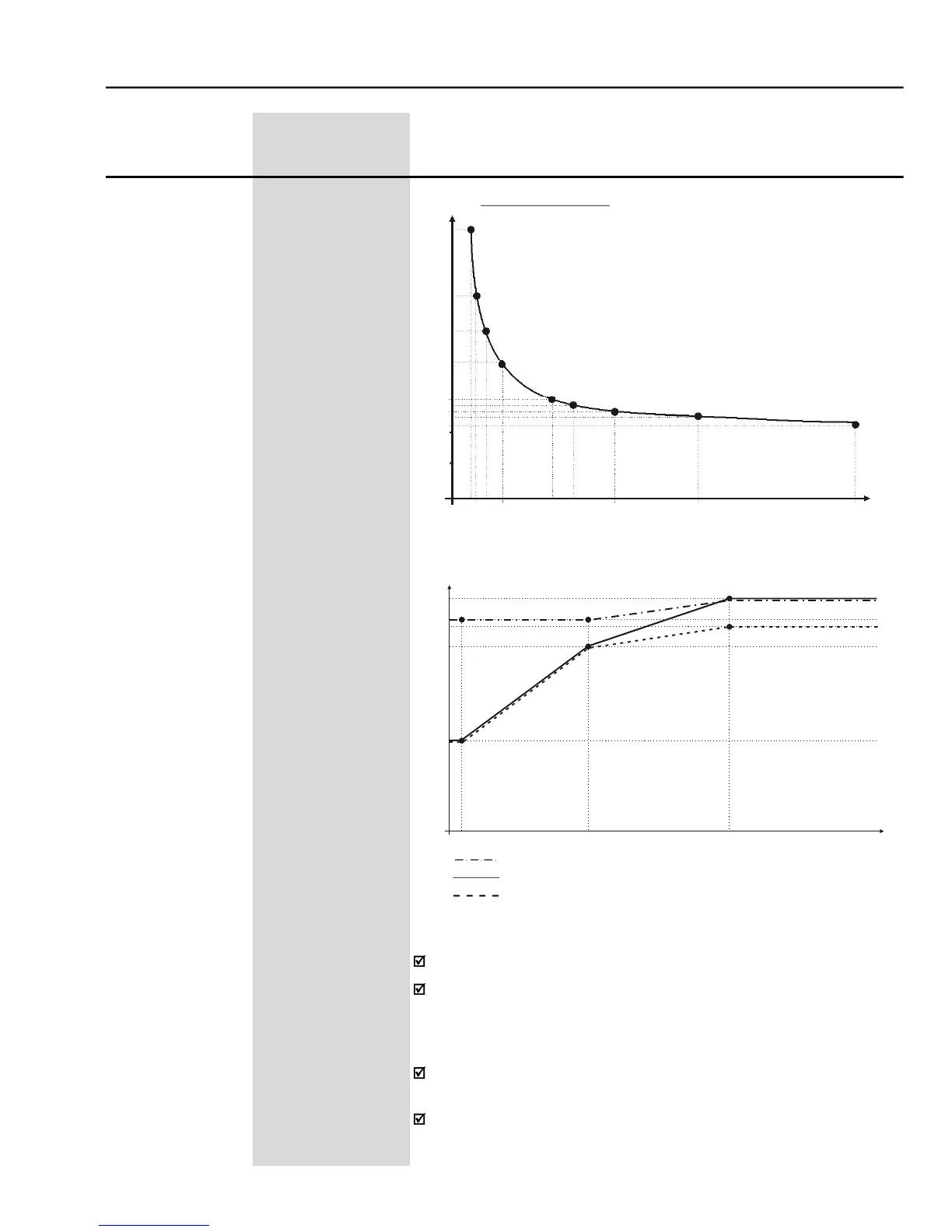
The Motor Overload Current(P156, P157 and P158) is the current level
above which the CFW-09 will consider the motor operating under
overload.The higher theoverload,the sooner theOverloadFaultE05will
ParameterP156(motoroverloadcurrentatbasespeed)mustbeset 10%
higher than theused ratedmotor current (P401).
The overload current is given as a function of the motor speed. The
parameters P156,P157 and P158 are the three points used to form the
overload curve, as shown in figure 6.18 with the factory default levels.
Curve for motor with separate ventilation
Curve for self-ventilated motor
Increased Protection Curve
- Ixt function - Overload detection
- Overload protection levels


 To Next Page