EasyManua.ls Logo

WEG CFW-09 - Page 137

WEG CFW-09
362 pages
Print Icon
To Next Page IconTo Next Page
To Previous Page IconTo Previous Page
Loading...
138
CHAPTER 6 - DETAILED PARAMETER DESCRIPTION
P155
0.00 to 650
DB Resistor Power
[ 2.60 ]
Rating
0.01 kW (< 9.99)
0.1 kW (> 9.99)
1 kW(> 99.9)
Adjusts the overload protection for Dynamic Braking resistor. Set it
according to the power rating of the DB resistor (in kW).
If the average power in the braking resistor during 2 minutes is higher
than the value set at P155, the inverter trips on an E12 fault.
Refer to
item 8.10.
Range
[Factory Setting]
Parameter
Unit
Description / Notes
P154
0.0 to 500
Dynamic Braking
[ 0.0 ]
Resistor
0.1
(
99.9)-
1
(
100)
Resistance value of the Dynamic Braking resistor (in ohms).
P154 = 0 disables the braking resistor overload protection. Must be
programmed to 0 when braking resistor is not used.
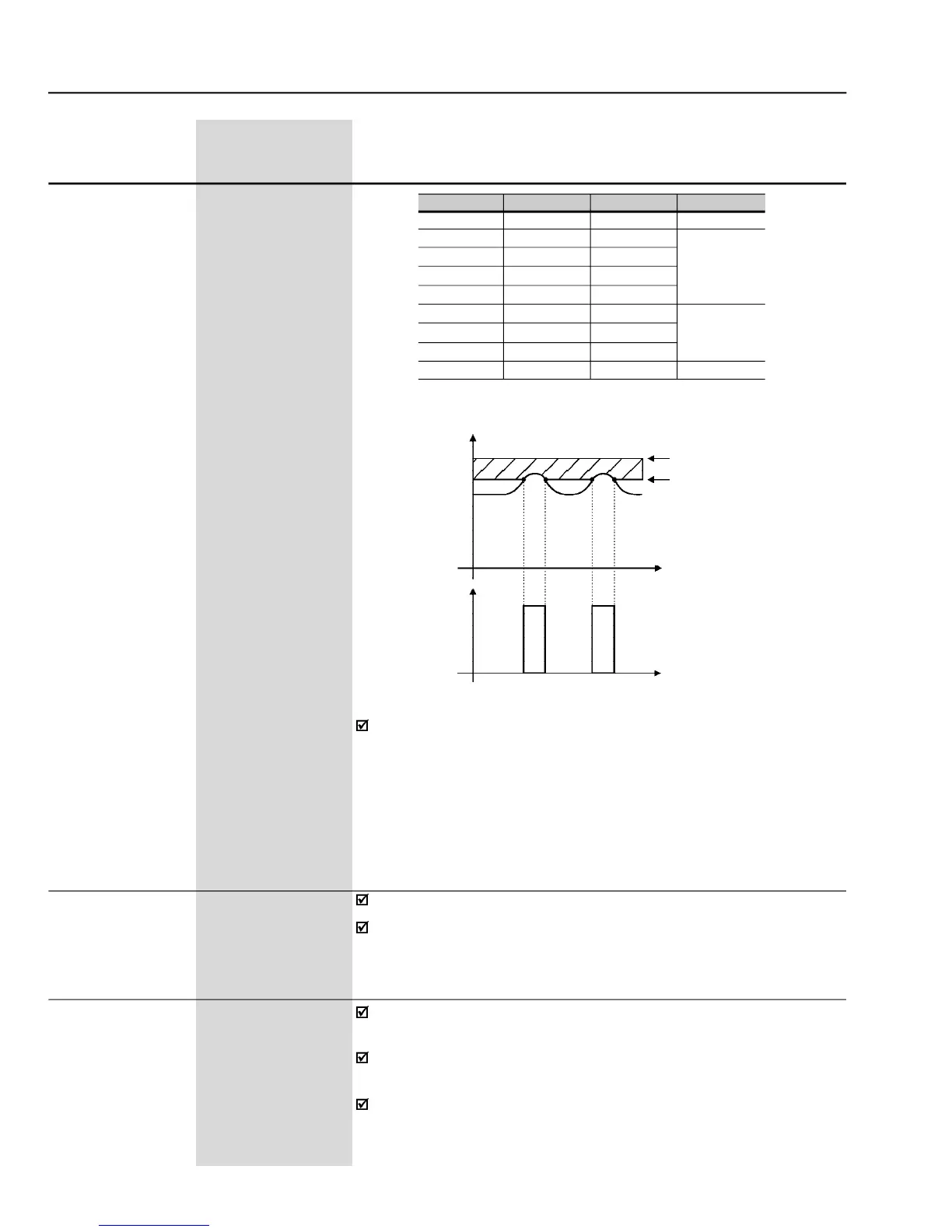
To actuate the Dynamic Braking:
Connect the DB resistor. Refer to
chapter
8.
Set P154 and P155 according to the size of the Dynamic braking
resistor.
Set P151 to its maximum value: 400 V (P296 = 0), 800V (P296= 1, 2,
3 or 4), 1000 V (P296= 5, 6 or 7) or 1200 V (P296 = 8), to avoid actuation
oftheDC Link VoltageRegulationbefore Dynamic Braking.
Inverter V
nom
220/230 V
380 V
400/415 V
440/460 V
480 V
500/525 V
550/575 V
600 V
660/690 V
P296
0
1
2
3
4
5
6
7
8
P153
375 V
618 V
675 V
748 V
780 V
893 V
972 V
972 V
1174 V
E01
> 400 V
> 800 V
> 1000 V
> 1200 V
E01 -Overvoltage Level
Dynamic Braking Level
Time
Time
DB Resistor
Voltage
Ud
Ud
P153
Nominal
DC Link Voltage (Ud) (P004)
Table 6.9
- Recommended settings of the dynamic braking actuation
Figure 6.16
- Curve of the dynamic braking actuation
678 to 800 (P296 = 3)
[ 748 ]
1 V
739 to 800 (P296 = 4)
[ 780 ]
1 V
809 to 1000 (P296 = 5)
[ 893 ]
1 V
885 to 1000 (P296 = 6)
[ 972 ]
1 V
924 to 1000 (P296 = 7)
[ 972 ]
1 V
1063 to1200 (P296 = 8)
[ 1174 ]
1 V

Table of Contents