EasyManua.ls Logo

WEG CFW-09 - Page 144

WEG CFW-09
362 pages
Print Icon
To Next Page IconTo Next Page
To Previous Page IconTo Previous Page
Loading...
145
CHAPTER 6 - DETAILED PARAMETER DESCRIPTION
While the OptimalBrakingis operating, P169 limits the maximum output
current in order to produce the braking forward torque (refer to P151).
Refer to the description for P169 above.
Range
[Factory Setting]
Parameter
Unit
Description / Notes
where:
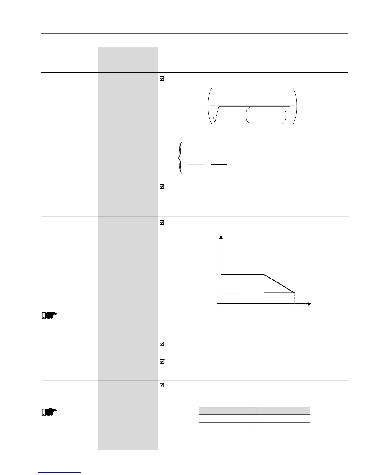
The maximum torque produced by the motor is given by:
Speed
Torque current limitation as a function of the speed:
P170/P169
Torque Current
This function is disabled while the value of P171/P172 is equal to or
greater than the value of P169/170.
P171 and P172 operate also during the optimal braking by limiting the
maximum output current.
P134
Synch. Speed x P180
100
Figure 6.22
– Operation curve of the torque limitation at maximum speed
P172
0 to 180
Maximum Reverse
[ 125 ]
Torque Current at
1 %
the Maximum Speed
(N = P134)
P171
0 to 180
Maximum Forward
[ 125 ]
Torque Current at
1 %
the Maximum Speed
(N = P134)
P172/P171
P173 = 0
P173 = 1
These para-
meters (P171 and
P172) are shown on
the
display(s)only
when
P202 = 3 or 4
(VectorControl)
P173
0 or 1
Type of Curve for the
[ 0 ]
MaximumTorque
-
Itdefinestheoperationcurveofthe torquelimitation atthefield-weakening
region. Refer to figure 6.22.
This para-
meter is show on
the
display(s)only
when
P202 = 3 or 4
(VectorControl)
P173
Curve Type
0
Ramp
1
Step
Table 6.11 -
Curve type of the maximum torque
Tmotor (%) =
P295 x
P169
x K
x 100
100
(P401)
2
-
P410 x P178
2
100
K =
1 for N
Nrated
Nrated
x
P180
for N >
Nrated
N 100

Table of Contents