CHAPTER 6 - DETAILED PARAMETER DESCRIPTION
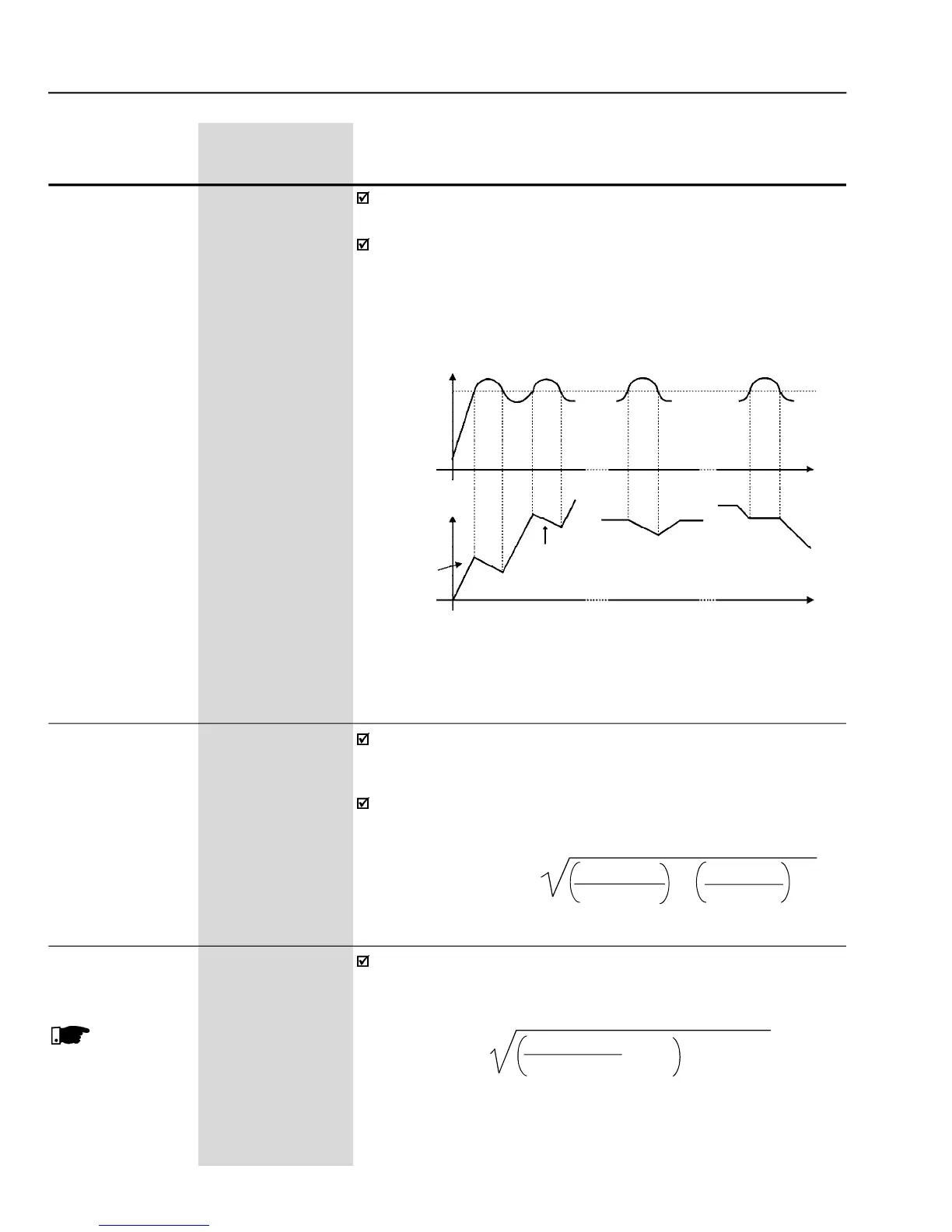
This parameter limits the motor output current by reducing the speed,
which avoids motor stalling under overload conditions.
As the motor load increases, the motor current also increases. When
this current exceeds the value set at parameter P169, the motor speed
is reduced (by using the deceleration ramp) until the current value falls
below the value set at P169. The motor speed is resumed when the
overload condition stops.
- Curves showing the actuation of the current limitation
This parameter limits the value of the component of the motor current
that produces forward torque. The setting is expressed as a percentage
value of the inverter rated current (P295 = 100 %).
The values of P169/P170 can be calculated from the maximum desired
value for the motor current (Imotor) by using the following equation:
This parameter limits the value of the component of the motor current
that produces reverse torque. While operating in torque limitation, the
motor current can be calculated by:


 To Next Page