CHAPTER 6 - DETAILED PARAMETER DESCRIPTION
The descriptionAI1’as apposed toAI1 refers to the analogue signal after
scaling and/or gain calculations have been applied to it (Refer to figure
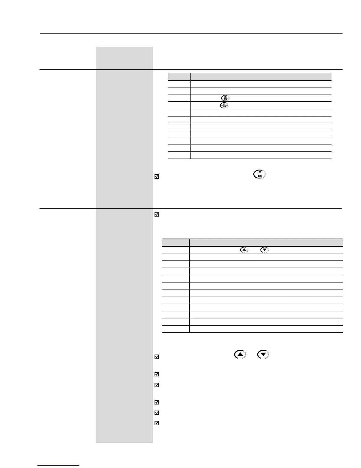
In the factorydefault setting, the key
of the Keypad (HMI) will select
Local or Remote Mode. When powered up, the inverter starts in Local
LOCAL/REMOTE Speed Reference Selection
Analog InputAI1' (P234/P235/P236)
AnalogInputAI2' (P237/P238/P239/P240)
AnalogInputAI3' (P241/P242/P243/P244)
Analog InputAI4' (P245/P246/P247)
Sum of the Analog Inputs AI1' + AI2' > 0 (Negative values are zeroed)
Sum of the Analog Inputs AI1' + AI2'
Electronic Potentiometer (E.P.)
Multispeed (P124 to P131)
Thereferencevaluesetbythe
keysiscontainedinparameter
Details of the Electronic Potentiometer (E.P.) operation in figure 6.37m).
When option 7 (E.P.) is selected, program P265 or P267= 5 and P266 or
When option 8 is selected, program P266 and/or P267 and/or P268 to 7.
When P203 = 1 (PID), do notusethe reference via E.P. (P221/P222 = 7).
WhenP203 = 1 (PID), thevalue programmedin P221/P222becomesthe
LOCAL/REMOTE speed reference selection
Key of the Keypad (HMI) (LOCAL Default)
Key of the Keypad (HMI) (REMOTE Default)
Digital inputs DI2 to DI8 (P264 to P270)
Serial (Local Default) - SuperDrive or incorporated Modbus
Serial (Remote Default) - SuperDrive or incorporated Modbus
Fieldbus (Local Default) - Optional Fieldbus board
Fieldbus (Remote Default) - Optional Fieldbus board
PLC (L) - Optional PLC board
PLC (R) - Optional PLC board