CHAPTER 6 - DETAILED PARAMETER DESCRIPTION
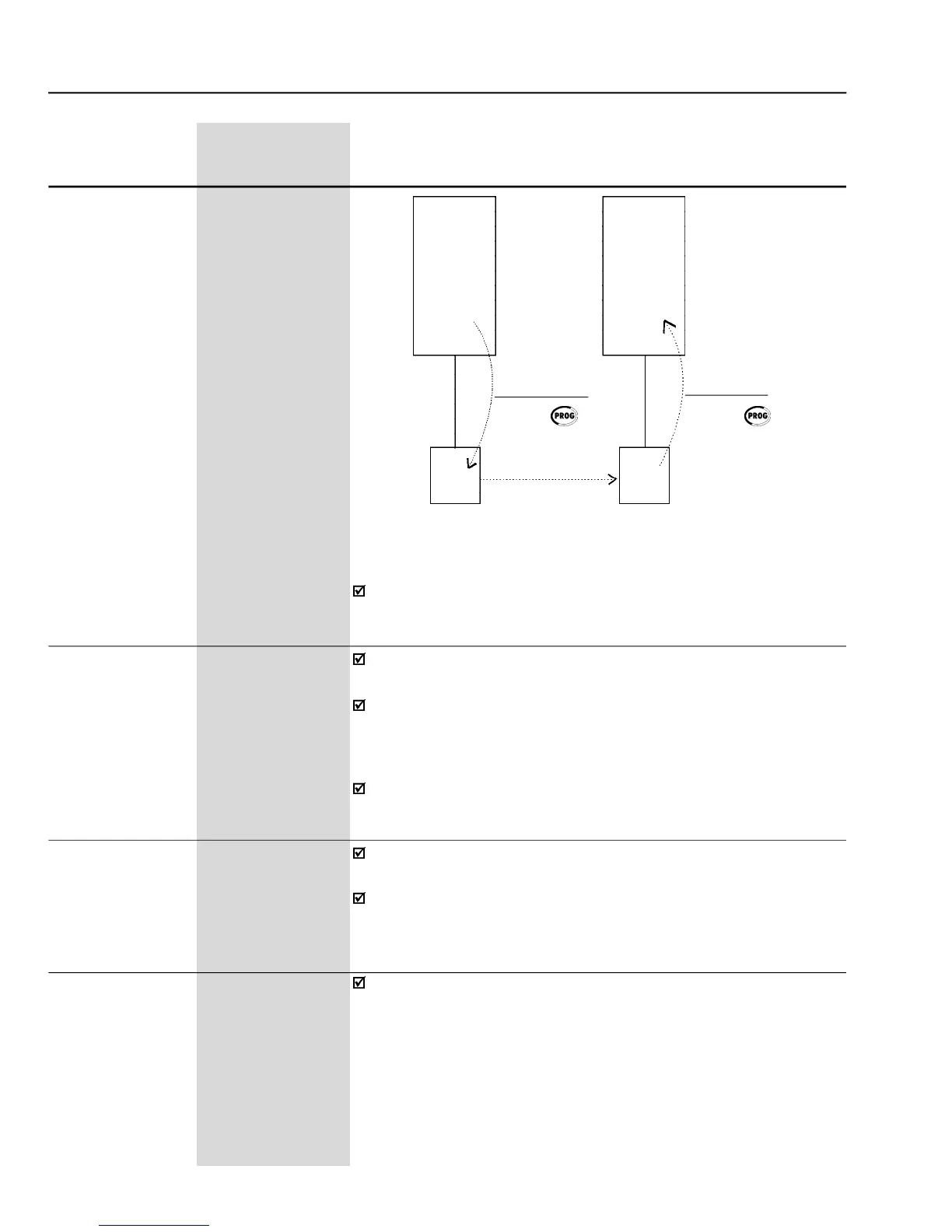
-Copying the parameters from the “Inverter A” to the “Inverter B”
These parameters are useful only for inverters provided with a keypad
The engineering unit of the speed reference is composed of three
characters, which will be displayed on the indication of the Speed
Reference (P001) and Motor Speed (P002). P207 defines the left
character, P216 the center character and P217 the right character.
For more details, refer to Parameter P207.
While the Keypad runs the reading or writing procedures, it cannot be
This parameter is useful only for inverters provided with a keypad with
It allows the adjustment of the LCD Display contrast. Increase/decrease
the parameter content to obtain the best contrast.
Defines the source of the LOCAL / REMOTE selection command.