CHAPTER 8 - CFW-09 OPTIONS AND ACCESSORIES
ENCODER CONNECTION: Refer to item 8.2.
The EBA board is installed on the CC9 control board, secured with spacers
and connected via terminal blocks XC11 (24 V) and XC3.
For the CFW-09 Size 1 Models (6A, 7A, 10Aand 13
4A, 5.5Aand 9A/380-480 V) the plastic cover must be removed to install the
Set the board configuration via S2 and S3 dip switches (Refer to
Carefullyinsert terminalblock XC3 (EBA) into the female connector XC3
of the CC9 control board. Check that all pins fit in the XC3 connector;
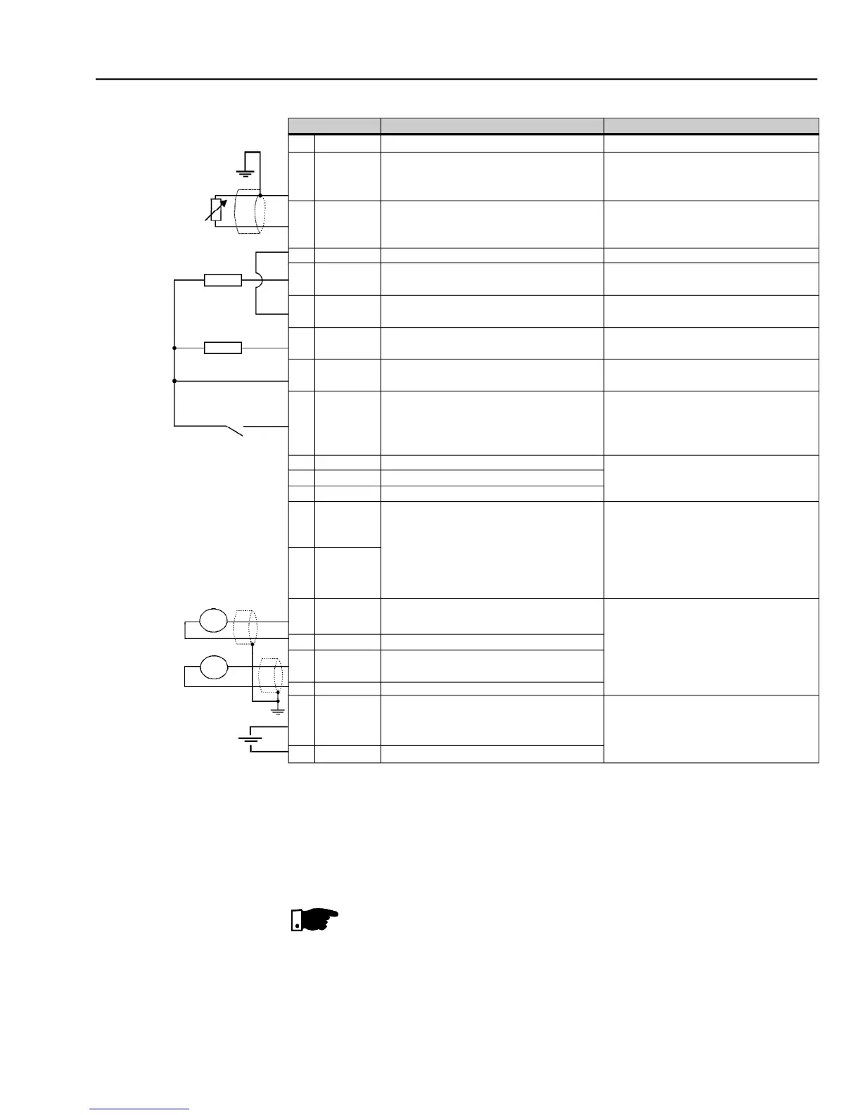
– XC4 terminal block description (EBA board complete)
Motor Thermistor Input 1 - PTC1
(P270 = 16 refer to figure 6.33). As DI
normal refer to P270 - figure 6.34.
Motor Thermistor Input 2 - PTC2
(P270 = 16 refer to figure 6.33). As DI
normal P270 - figure 6.34.
0 V reference of the 24 Vdc source
Transistor output 1: Not Used
Common point for Digital Input DI7
and Digital Outputs DO1 and DO2
Transistor Output 2: Not Used
Power Supply for the digital inputs/
Isolated Digital Input: Not used
Analog input 4: Frequency Reference
Reference for Analog Output
Reference for Analog Output
Analog Output 4: Motor Current
Avaliable to be connected to an external
power supply to energise the encoder
V reference of the external
Reference to DGND (DI8) through a
Isolated, open collector, 24 Vdc, 50 mA
max., required board (RL)
Isolated, open collector, 24 Vdc, 50 mA
max., required board (RL)
Input Current.: 11 mA @ 24 Vdc
Isolated RS-485 serial Port
Differential analog input programmable
or (0 to 20) mA / (4 to 20) mA
lin.: 14 bits (0.006 % of full scale range)
[(0 to 20) mA / (4 to 20) mA]
Scales: refer to P255 and P257.
lin.: 14 bits (0.006 % of
External power supply: 5 V to 15 V
Consumption: 100 mA @ 5 V