CHAPTER 8 - CFW-09 OPTIONS AND ACCESSORIES
Indication LEDs for the status of the EtherNet/IP network
the module is connected to another device on the network (typically a
: the module is not connected to another device.
No power applied o the module.
The module is operating correctly.
the module has not been configured.
A minor recoverable error has been detected.
A major internal error has been detected.
The module has no power or no IP address has been assigned.
the module has at least one established Ether
ections established to the module.
One or more of the connections in which this module is the target has
The module has detected that its IP address is already in use.
indicates that a packet has been received and/or transmitted.
Configuration of the Network Master Data
For the master configuration, besides the IP address used by the EtherNet/IP
board, it is necessary to indicate the number of I/O instances and the quantityof
dataexchangedwith themasterineach instance. Forthe CFW-09withAnybus-S
EtherNet/IP board, the following values must be programmed:
Data amount programmable through P309: it may be 2, 4 or 6 words with 16
The EtherNet/IPboard for the CFW-09 is described in the network as a Generic
Ethernet Module. By using these configurations it is possible to program the
network master so that it communicates with the inverter.
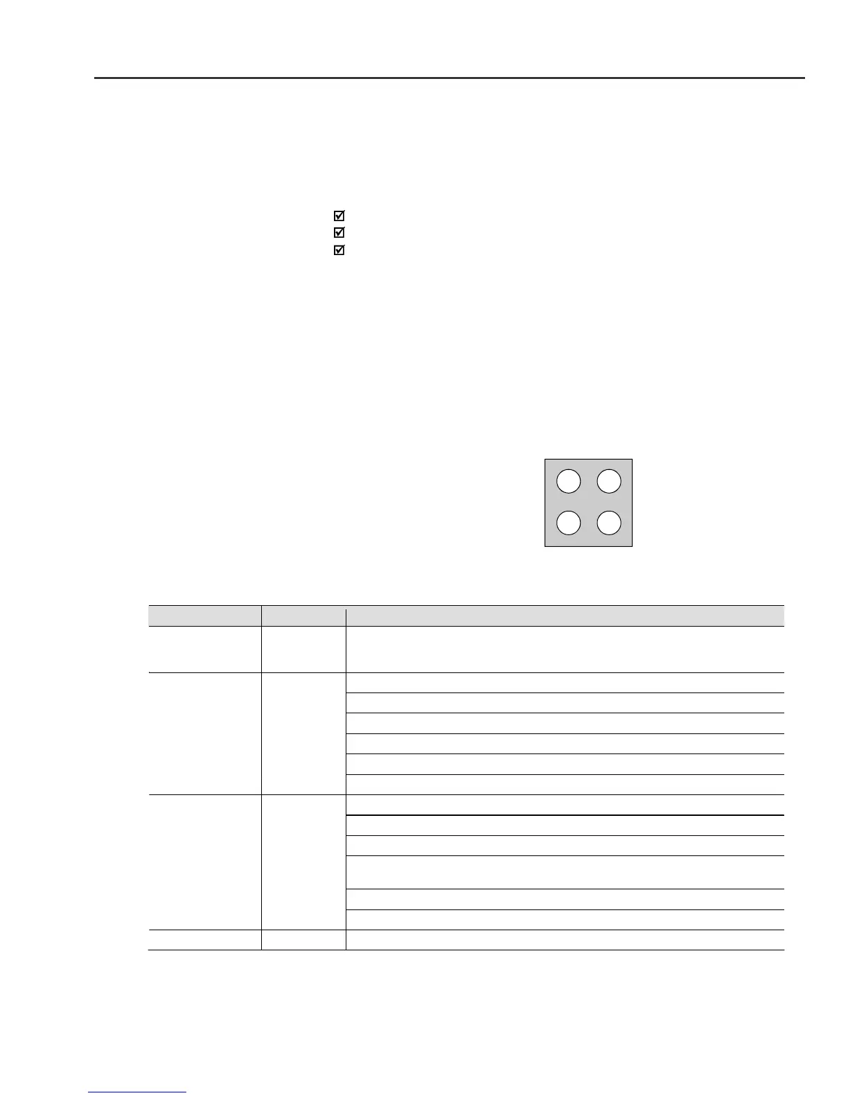
The communication board has four two-color LEDs located on the right bottom
corner to indicate the module and the network status.