Maintenance1132−2/A1
Winterthur Gas & Diesel Ltd.
6/ 14
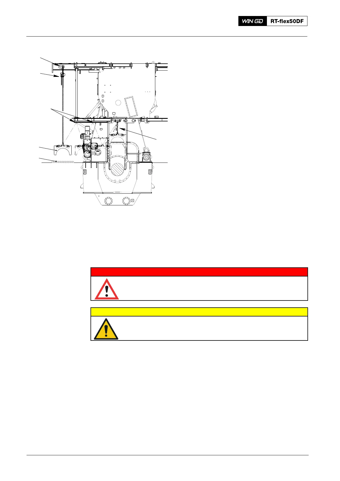
17) Attach the manual ratchet (H1, Fig. 8)
to the main bearing cover and the
attachment point (3) as shown.
18) Operate the manual ratchets (H1, H2)
between the attachment rings in the
gallery to move the main bearing
cover (2) to the fuel side.
19) Attach the chain block (H3) to the main
bearing cover (2) (when the main
bearing cover is directly below the
attachment point (3) in the gallery).
20) Remove the manual ratchets (H1, H2).
Note: When you do step 21), make sure
that you do not cause damage to
the bearing shell (2) and the
surfaces of the main bearing cover
(3).
21) Operate the chain block (H3) to lower
the main bearing (1) on the wooden
underlay.
4. Main Bearing Shell − Removal
4.1 Hydraulic Jacks − Installation
WARNING
Injury Hazard: Before you operate the turning gear, make sure
that no personnel are near the flywheel or in the engine.
CAUTION
Damage Hazard: Do not remove two adjacent main bearing shells
at the same time. Damage to the engine can occur.
1) Remove the work platform (94143).
2) Operate the turning gear to turn the applicable crank to the exhaust side
approximately 90_ after TDC.
3) Lock the turning gear to prevent movement.
4) Install the work platform (94143).
2016
Main Bearing − Removal and Installation
Fig. 8
H1
H3
H2
2
1
3