Maintenance
1132−2/A1
Winterthur Gas & Diesel Ltd.
7/ 14
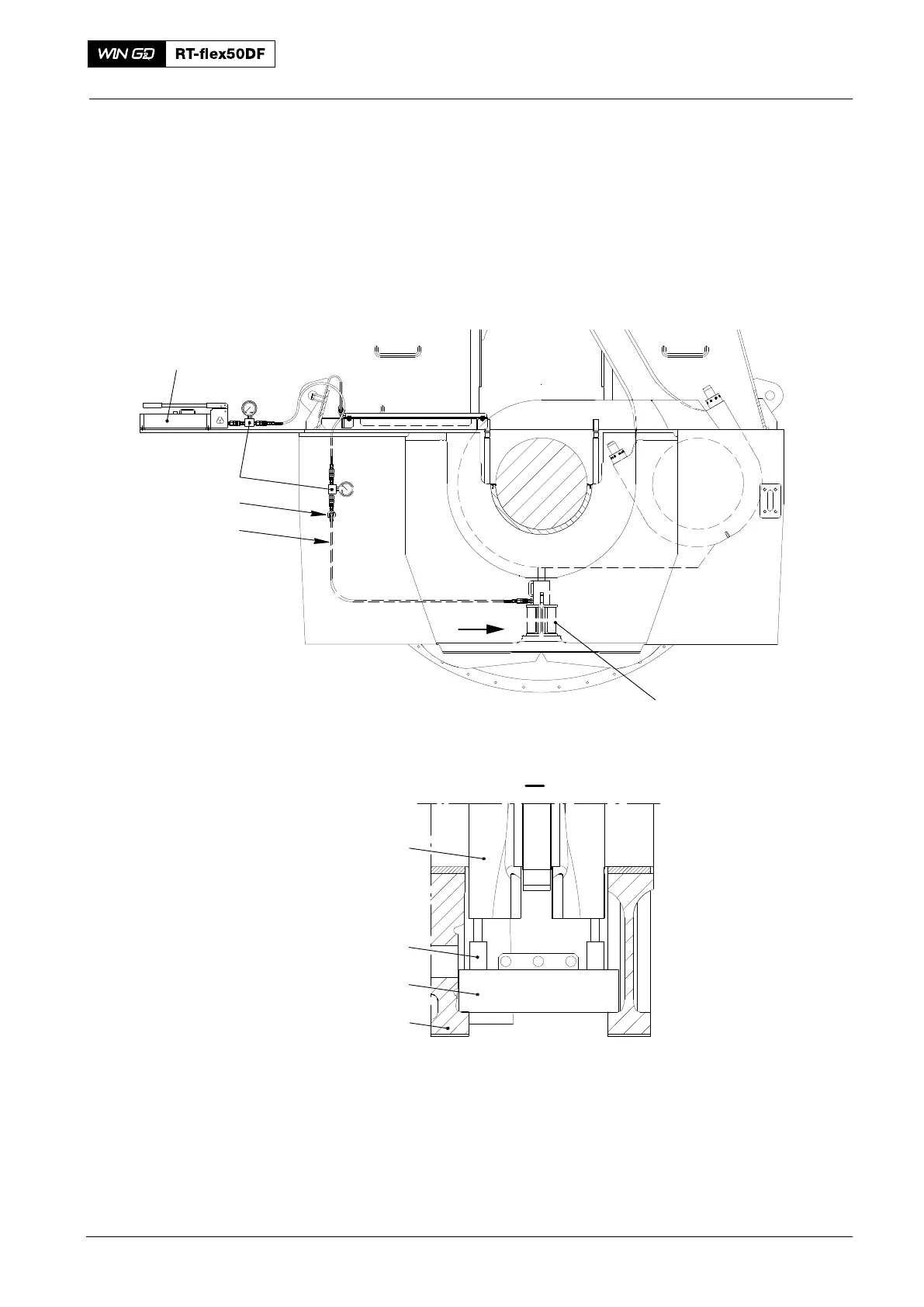
Note: When you remove the bottom bearing shell No. 1, you must use the jack
(1, Fig. 9) to hold the weight of the flywheel. To give protection to the
flywheel teeth, put a copper or aluminum plate between the jack and the
flywheel.
5) Put the support (94141) in position on the two main bearing girders (2) parallel to
the engine axis.
6) Put the hydraulic jacks (94936) on to the support (94141).
7) Connect the HP oil pump (94931) to the hydraulic jacks (94936).
013.213/05
013.214/05
I
I
94934A
94931
94934
94935
94936
1
2
94141
1
Fig. 9
Main Bearing − Removal and Installation
2016